December 2025

Solenoid Valves
Blog

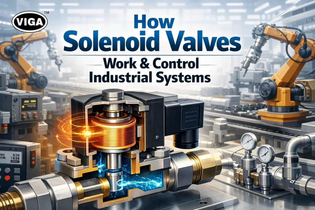
How Solenoid Valves Work & Control Industrial Systems

One Tiny Coil That Controls the Whole System — Inside the World of Solenoid Valves! The Power of a Tiny Coil The efficiency of every modern factory, laboratory, and mechanized facility stands or falls based on one often-overlooked, small piece of hardware: the Solenoid Valve. Look, the reality is simple. As control systems professionals, install a vast, intricate automation architecture—network protocols, advanced PLCs, sophisticated sensor packages—and what brings all that expensive logic down? Usually, a three-inch component. By faithfully and reliably standing as the precise point where electrical thought instantly translates into powerful mechanical force. See the stories about entire automotive final assembly lines coming to a screeching, emergency halt, only to find the root cause was one tiny coil on an upstream cylinder’s air valve that decided to stop taking current. The economic loss of that stoppage makes the choice of the correct component paramount, underscoring its foundational role in all Industrial Automation. This small device is far more than an on/off switch; it’s the high-speed flow control valve that governs literally everything that moves, making it indispensable for system reliability and performance. Getting its application wrong means you’ve built your highly tuned race car on square tires. What Is a Solenoid Valve? So, what is a solenoid valve, at its core? It’s the ultimate electro-mechanical actuator, designed for rapid, remote control over the flow of any type of media. In plain terms, it uses the science of magnetism to operate a physical plug (a seal or diaphragm) that allows fluid, air, or gas to flow through a specific line. To simplify the expertise: Think of a solenoid valve as an intelligent gatekeeper, controlled entirely by a weak electrical pulse. This is an absolutely crucial component within any fluid control systems, where we’re managing materials that might be hazardous, expensive, or under extreme pressure. Two main parts in any good solenoid assembly, establishing its nature as an electromagnetic valve: The Coil (The Logic): This is the core. It is the tightly wound magnet wire. It receives its digital command (typically from 12VDC to 240VAC). This coil, when energized, immediately converts electrical current into usable magnetic force. The Valve Body (The Actuator): This is the metal or composite structure containing all the hydraulic bits: the fixed ports, the sealing orifice, the spring, and the internal ferromagnetic steel rod known as the plunger or armature. In pneumatic systems, solenoids handle high-pressure air used to operate actuators; conversely, they are used for simple on/off commands on a municipal water line. That universality, allowing one design principle to cover everything, is its main engineering strength. How a Solenoid Valve Works The key to mastering this hardware lies in fully grasping the simple physics driving the solenoid valve working principle. The objective is to produce enough electromagnetic force to swiftly defeat the combined hydraulic pressure and the spring’s stiffness—all without a huge power draw. Let’s trace the power flow in a standard Normally Closed (NC) valve configuration. This should provide the solenoid valve coil working explained clarity you need: Resting State: Without power, the engineered return spring is actively pushing the plunger downwards, keeping the durable seal tightly compressed onto the flow orifice. The hydraulic force of the media line is also working in the same direction, further securing the closed seal. Flow is firmly blocked. Electrical Activation: The PLC sends an “open” signal. The solenoid valve coil immediately receives its specific operating current. Magnetic Field Genesis: Instantly, current flow transforms the coil into a temporary electromagnet. The goal isn’t gentle power—the solenoid must rapidly develop a powerful magnetic pull concentrated on the center of the coil’s core. The Plunger Movement: This immense magnetic pull vertically overcomes the tension of the return spring (which is quite strong) and simultaneously defeats the internal hydraulic pressure. The plunger is pulled forcefully upwards, a purely physical translation of energy. The Flow Open Process: As the plunger ascends, it pulls the sealing mechanism away from the valve seat, clearing the path. Media immediately flows from the input to the output. This is precisely how solenoid valves control flow at its critical juncture. Deactivation (Close Command): The electrical current is instantly removed. The magnetic field immediately and entirely collapses. Without that counteracting magnetic force, the dedicated return spring immediately snaps the plunger back down, seating the seal perfectly and restoring the flow barrier. The near-zero latency of this operation makes it perfect for fast-action valve actuation. Why Solenoid Valves Are the Backbone of Automation In the running automated processes, the speed, precision, and simplicity that solenoids offer have no effective parallel for basic binary (on/off) media control. Without them, Industrial Automation it would grind to a clumsy halt. Exceptional Response Time: The best solenoid valve units are built to shift and seal in under 20-30 milliseconds. Compare that to the two-second operation time of a standard pneumatic actuator moving a larger butterfly valve! That high-speed sequencing capability is fundamental to keeping high-output machinery running effectively. Simple Remote Control Interface: A great strength of the solenoid valve in automation is its easy interface. Your sophisticated $100,000 process controller can reliably command thousands of individual, low-voltage solenoid valves using simple digital output cards. This makes distributed, large-scale flow control management highly affordable. The Crucial Safety Interlock: This is a safety factor. NC Solenoid Valves provide the simplest and most cost-effective fail-safe condition possible: no power equals no flow. Linking these devices directly to an emergency stop or safety circuit ensures that if all power is dropped, hazardous motion, pressure, or chemical supply lines are automatically cut. This adherence to high standards for safety risks makes them preferred process control valves across many applications. Types of Solenoid Valves Explained Clearly There is no one “right” solenoid—only the right type for the application. The selection requires matching the application’s demand (failure state and flow dynamics) to the valve’s physical capabilities. Knowing the difference here saves both time and major capital investment. Core Classification: The Failure State Choosing between the two fundamental options dictates how your entire system behaves in a power failure. Type of Valve De-Energized Status (Default State) Expert Tip/Use-Case Priority Normally Closed (NC) Physically Closed: No flow, firmly sealed. Mandatory when a controlled shut-off upon power failure prevents product loss or is safer (e.g., closing fuel lines, isolating power cylinders). Normally Open (NO) Physically Open: Flow is

Pneumatic Cylinder
Blog

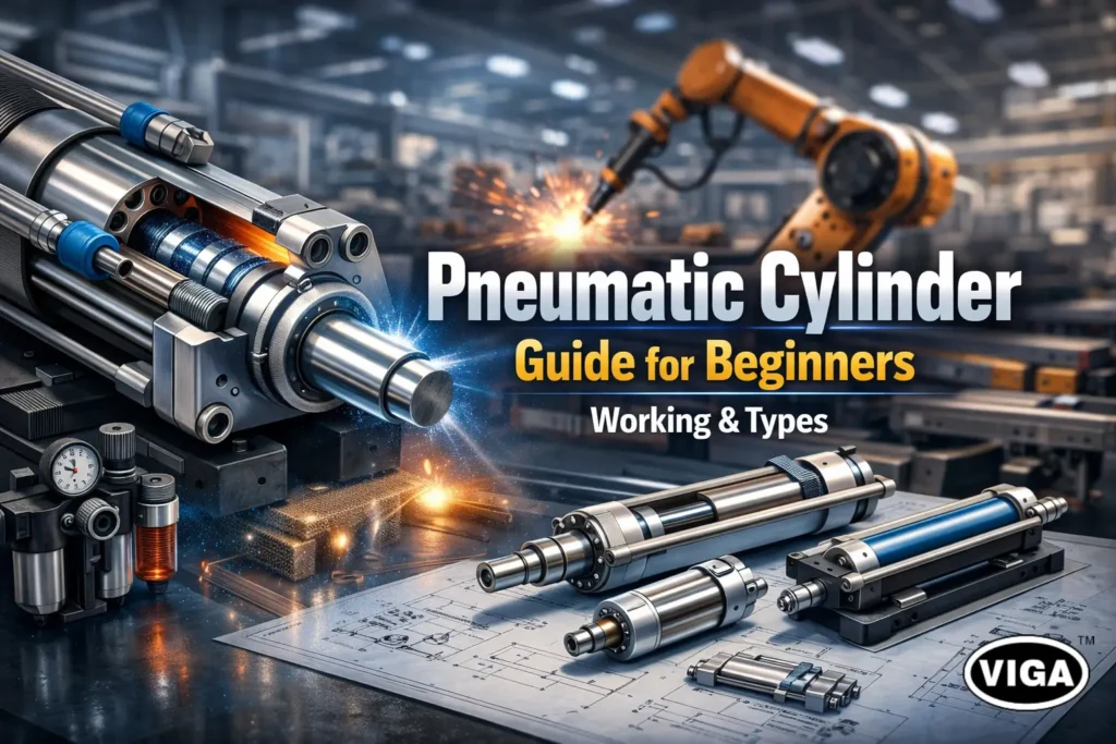
Pneumatic Cylinder Guide for Beginners | Working & Types

They Move Everything — A Beginner’s Guide to Pneumatic Cylinders That Do All the Work! The Power Behind Industrial Movement Step one foot onto a modern automated factory floor and one machine quickly becomes the star: the humble, hardworking cylinder. They’re absolutely everywhere. Clamping this piece, shoving that item down the line, holding something tight for a weld. If it’s fast and straight-line, chances are a pneumatic cylinder is driving it. The entire principle of reliable industrial automation rests on these precise, powerful, and ridiculously common movements. No matter how clever the electronics or robotics get, at some point, you still need reliable physical force, right? That force is delivered, quietly, efficiently, and cleanly, by the system of air-powered workhorses we’re talking about here. For anyone who’s ever had to spec a new assembly jig or simply diagnose a slow packaging machine, you quickly learn you have to know these cylinders cold. In this guide, we’re going through all of it. We’ll break down the very simple pneumatic cylinder working principle, clear up confusion on component selection, and share some real-world secrets on why air quality affects cylinder life. No more guessing games! What Is a Pneumatic Cylinder? Simply put, it’s the motor for straight-line pushing and pulling. A pneumatic cylinder is the machine element that grabs air pressure from the compressor—that costly utility you run all day—and turns it into clean, controllable physical movement. Forget formal descriptions. Think of it like this: A heavy, rugged steel tube (the cylinder) is completely sealed off. Inside is a strong piston connected to an external rod. You shove high-pressure air into one end, and it instantly forces the rod out the other end. That’s it. It’s an air-powered actuator. In a catalogue, you’ll see the official title of a linear motion actuator, because that rod doesn’t spin; it goes back and forth. You won’t use these for driving conveyors—you’ll use them for things like operating machine safety gates or punching small holes. Any job that requires a single, powerful push or pull stroke is best handled by this kind of pneumatic actuator. They are rugged simplicity. How Pneumatic Cylinders Work The elegant thing about the pneumatic cylinder working principle is that it is a pure demonstration of pressure: when force has nowhere to go but one direction, it goes that direction with all its power. Role of Compressed Air The air comes from your facility’s system, but its path is strictly controlled by valves. That valve directs the high-pressure compressed air actuator energy toward the cylinder’s chambers, effectively deciding where the muscle power is needed at that moment. The moment that high-pressure source is hooked up, the system is primed. Piston and Cylinder Movement The sealed, interior piston is what actually gets the job done inside the casing. It’s sitting in there, essentially separating the volume of the tube into a ‘forward’ side and a ‘back’ side. You want to make the rod go out? You create more pressure on the back side. Conversion of Air Pressure into Linear Force Your directional valve clicks, opening the flow and dumping air at high pressure into the chamber behind the piston head. At the same instant, the front chamber air needs a fast path out—that air is instantly released through a silencer. Since the force against the back of the piston is massive and the force against the front of the piston has gone to zero, the pressure differential creates a swift, continuous linear force until the rod hits the end stop. It’s all about creating and managing a massive imbalance. Fast and dependable every time. Main Components of a Pneumatic Cylinder If you’re expected to maintain these, you need to know which parts are disposable and which parts are critical structure. When checking component specifications, pay close attention to the structural aspects. Cylinder Barrel: It’s the fixed body of the tool. Key design point: the inner surface must be flawless, with zero nicks or rust spots, or your seals won’t last ten minutes. Piston and Piston Rod: The piston is the round head that air pushes. The piston rod is the thick, hardened steel bar that actually extends out into the machinery. A bent rod is an almost instantaneous trip to the scrapyard. End Caps (Heads): These are the structural lids that seal the unit shut and provide the necessary Air Ports to feed pressure. They often contain the mounting threads and shock absorbers. Seals and Bearings: These two wear parts define the entire lifespan. The Seals are elastomeric rings that contain the pressure, and the Rod Bearings are the bronze collars that ensure the rod stays straight. Failures in this area mean immediate loss of power. Types of Pneumatic Cylinders Explained Simply Which type you use boils down to how complex the application is—can you use simple return action, or do you need control for both movements? Single-Acting Pneumatic Cylinders This cylinder has only one power stroke: the push (or the pull). It only uses one air line. When you stop supplying air, a pre-installed return spring takes over, shoving the piston back to the home position. Key trade-off: It saves on air consumption, but the piston has to work against that internal spring force, meaning its overall pushing strength is significantly less than the double-acting unit. Simple for tasks like quick door openings. Double-Acting Pneumatic Cylinders This is the machine’s choice for precision control. A double-acting pneumatic cylinder has power on both ends: air to push out, and separate air line control to pull it back in. Key advantage: Provides maximum force for the cylinder’s size in both directions. Essential for pneumatic motion control applications that require high force throughout the entire stroke length. It does, however, use twice the volume of compressed air. Rodless Pneumatic Cylinders Imagine trying to stabilize a long piston rod when moving a 400-pound load over a 15-foot distance. Impossible. The rodless pneumatic cylinders solved this problem by sealing the air in the barrel but letting an external sliding saddle do the heavy movement along a guide. They save tremendous space and are vital in large gantry and positioning systems. Where Pneumatic Cylinders Are Used These units are the quintessential industrial automation components because their usage is so widespread and reliable. Manufacturing and Assembly Lines: Their high

Why Your Air Compressor Needs the Right Air Filter
Blog

Why Your Air Compressor Needs the Right Air Filter

Let’s start with a foundational, critical fact that is often missed in the chaos of the shop floor: Your machinery lives or dies by the quality of its air. Think about your own lungs—they require clean, filtered air to survive and function optimally. Now, translate that necessity to your complex industrial system. For the industrial world, the compressed air supply is an omnipresent utility, the literal engine behind countless operations. The crucial comparison here is immediate and profound: If humans can’t survive polluted air, neither can your compressor. We see the damage all the time: that high-value CNC machine whose valves are sticky, that sudden spike in abrasive dust clogging a critical high-precision solenoid. This is the handiwork of dirty compressed air, the subtle saboteur lurking in the lines. The only thing standing between microscopic, corrosive filth and your most expensive equipment is the unsung hero—the Air Compressor Filter. Take, for instance, a large factory where metal filings and water vapour are drawn in every second. When those impurities meet high pressure and move into the pneumatic valves, it inevitably results in damaging wear and unplanned downtime. This happens because why compressor needs air filter isn’t simply about capturing dirt—it’s about preserving a controlled operating environment. Neglecting a robust compressor air filtration strategy is choosing risk over reliability. In this guide, we cut through the confusion and explain exactly why and how your filtration strategy determines your company’s uptime and financial health. A perfectly functioning, long-lasting system must deliver demonstrably clean compressed air—that much is certain. Why Clean Air Matters in Compression Systems We rely on compressed air so fundamentally that we often stop thinking about what it actually is. It’s often referred to as the “industrial oxygen”, indispensable power that drives robotic actuators, sorting lines, and material handling systems. Yet, air that enters your system is rarely pure; it’s loaded with everything from local street dust to pollen, and worst of all, latent moisture. Here’s the danger: as the air volume is crushed from atmospheric pressure to the required system pressure, those atmospheric contaminants become intensely concentrated. The parts per million of moisture and dust is multiplied, effectively turning a mild atmospheric irritant into a corrosive, damaging cocktail inside your equipment. The real cost comes in the hidden breakdown that results in the costly effects of dirty compressed air. You get: Rusting components as water condenses downstream. Clogs formed by fine particulates and condensed oil aerosols. Wasted energy fighting back-pressure and flow restriction. An operation’s credibility and bottom line hang in the balance, requiring an immediate elevation of technical due diligence, what experts call a solid compressor air filtration program. What Exactly Is an Air Compressor Filter? If your compressor is the engine, the Air Compressor Filter is the specialized guardian standing between the volatile outside environment and your critical tools. It is, perhaps, most easily visualized as a super-industrialized version of your kitchen’s coffee filter, tasked with far more complex particle removal and chemical capture. What is the main role of an air compressor filter? Its three-fold primary purpose is: capturing solids, facilitating moisture separation, and adsorbing oil and solvent vapors. It isn’t merely a physical screen, but an engineered separator. In the physical setup of a Clean Compressed Air System, you don’t typically see just one filter; you see a ‘filter train.’ Filters are intentionally placed downstream from the compressor’s receiver tank. Why there? Because the compressed air needs time to cool down. As it cools, the hot vapour quickly turns back into liquid water (condensate and aerosols). It is far more efficient for the modern Air Compressor Filter to deal with liquid droplets and sticky residues than try to scrub pure gas. That staged, strategic installation is fundamental to running a professional Compressed Air System. How Dirty Air Damages Your Compressor & Pneumatic Tools When air contamination breaks through your primary defenses, the process moves instantly from productive function to guaranteed destruction. This rapid breakdown demonstrates why paying for clean air is simply smarter than paying for replacement parts. The problem boils down to abrasive damage and systemic clogs, both leading to catastrophic component stress. Internal Component Seizure and the Sandpaper Effect: Fine dust and dirt aren’t filtered, but they’re accelerated. They create a “sandpaper effect” inside air-driven components, increasing friction on critical seals, pistons, and rotors. The result? Premature wear, reduced stroke consistency, and seals that start leaking precious pressure. This mechanical damage confirms why clean air is so vital—otherwise, it’s instant Compressor Damage. The Ruin of Seals and O-Rings: High heat and consistent exposure to contaminated water condensate drastically accelerates the degradation of rubber and plastic seals. This failure manifests as countless, expensive leaks throughout your system. Once air is leaking, your system’s required run time increases exponentially to compensate, undermining overall compressor efficiency. Rapid System Failure and Clogging: Perhaps the most frustrating immediate Effects of Dirty Compressed Air is system stalling. Oil aerosols that condense in cool air lines combine with dust to create sticky sludge. This thick grime jams and obstructs the fine tolerance control components within critical spool and pilot valves, leading to near-immediate pneumatic system failure that requires hours of troubleshooting and manual valve teardown. Negating Tool Reliability: Let’s be honest: if you want to know how air filters protect pneumatic tools, look at the replacement bills. Unfiltered, dirty air voids warranties because manufacturers know that moisture and grime erode the finely tuned lubrication within an air tool, causing motors to bind up and bearings to rust prematurely, confirming that using Dirty Compressed Air on precision tools is financially suicidal. Types of Air Compressor Filters Any expert will tell you: if your filtration system uses a single element to do a complex, multi-layered job, you’ve set yourself up for early failure. Filtration systems rely on a tailored, step-by-step approach. Types of air compressor filters must be selected based on the specific type of impurity you are trying to mitigate, showcasing a depth of professional Expertise. Filter Type Primary Action / Location Contaminant Target Rationale for Use General Particulate First stage (bulk pre-filter). Large solid particle removal (dust, rust, dirt). Protects the more delicate, high-value filters downstream. Coalescing (General Duty) Middle stage. Oil aerosols, condensed water, and fine solids (up

Scroll to Top