Pneumatics Actuator Valves Explained | Types, Working & Uses
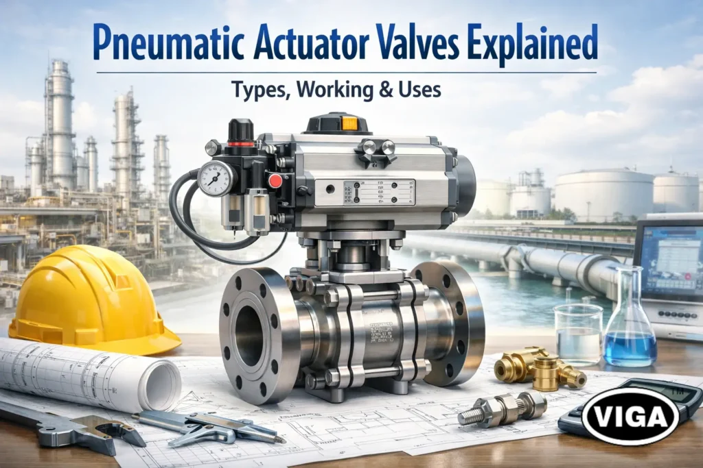
From Switch to Motion — How Pneumatic Actuator Valves Bring Automation Alive! A control signal traveling down a copper wire is just information. It has no muscle. It cannot stop thousands of gallons of water rushing through a treatment plant or shut down a high-pressure steam line in a fraction of a second. To turn that low-voltage data into physical action, industrial automation relies on the brute force of compressed air. Pneumatics actuator valves act as the conversion point between the digital control logic of a PLC and the heavy mechanical reality of piping systems. While electric servos grab the headlines for precision in robotics, the process industries—Oil & Gas, Chemical, Water, and Food Processing—run almost entirely on pneumatic actuation. This preference isn’t about nostalgia. It is about physics. Compressed air systems provide a density of force, speed of response, and inherent safety that electrical systems struggle to match at scale. For the engineer or plant manager, understanding these components is not just about knowing how to open a pipe; it is about understanding the primary safeguard between efficient production and operational failure. This technical guide dissects the mechanics of pneumatic valve automation, from the torque curves of scotch yoke actuators to the critical sizing calculations required to prevent stall conditions in the field. What Are Pneumatics Actuator Valves? Technically, there is no single component called a “pneumatic actuator valve.” It is an assembly—a marriage of three distinct pieces of hardware that must be compatible to function. The Valve Body: The wetted part that controls the media (Ball, Butterfly, Globe, or Gate). The Pneumatic Actuator: The aluminum or steel engine that sits on top, converting air pressure into torque (rotary) or thrust (linear). The Mounting Hardware: A critical, often overlooked link. This includes the mounting bracket and the drive coupling. These must strictly adhere to ISO 5211 standards to ensure the actuator turns the valve stem rather than shearing it off. When these three act in concert, driven by a pilot signal, they form the automated unit. Unlike a manual valve requiring an operator’s physical presence, or a solenoid valve which is limited to small diameters (typically under 2 inches), a pneumatic actuator valve system uses the facility’s “fourth utility”—compressed air—to drive large industrial loads with high reliability. The system scales effectively. The same 80 PSI air supply can actuate a tiny 1/2-inch sampling valve or a massive 48-inch pipeline shut-off valve; the only difference is the surface area of the piston inside the actuator. How Pneumatics Actuator Valves Work (Step-by-Step) The operating principle relies on the relationship: Force = Pressure × Area. Since plant air pressure is generally fixed (typically oscillating between 80 and 100 PSI), manufacturers generate more force by increasing the surface area of the internal pistons. The sequence of operation typically follows this path: Signal Initiation: The PLC (Programmable Logic Controller) or DCS (Distributed Control System) sends a command. This is usually a 24VDC discrete signal (for open/close) or a 4-20mA analog signal (for modulating control). Pilot Actuation: This electrical signal energizes a coil in the solenoid valve—commonly a 5/2-way or 3/2-way valve mounted directly to the actuator via a NAMUR interface. Air Injection: The solenoid spool shifts, directing air into the actuator’s pressure chamber. Energy Conversion: As the chamber fills, air pressure builds against the piston face. Once the force generated exceeds the “breakaway torque” of the valve (plus the friction of the actuator itself), movement begins. Motion Transfer: In Rack and Pinion designs, the pistons push outward, rotating a central gear. In Linear designs, the piston pushes a stem directly down. Cycle Completion: As the valve reaches its travel limit (open or closed), the air pressure maintains the position (in double-acting units) or compresses a spring bank (in single-acting units). Single-Acting (Spring Return) vs. Double-Acting This is the most critical logic distinction in the specification process. Double-Acting (DA): Uses air to open and air to close. It gives the operator control over both strokes and is physically smaller and cheaper because there are no springs taking up internal volume. However, upon air failure, the valve acts unpredictably—it stays where it is, or drifts with flow pressure. Single-Acting (Spring Return / SR): Uses air to power the valve in one direction (usually compressing a heavy internal spring). When air supply is cut—intentionally or via accident—the mechanical spring energy drives the valve back to its “fail” position (Fail Close or Fail Open). This mechanical guarantee makes SR actuators the mandatory choice for active safety systems. Types of Pneumatic Actuator Valves Not all motion is the same. Engineers categorize these valves based on the mechanical movement required to cycle the flow. 1 Based on Actuator Motion Rotary Actuators (Quarter-Turn) Used for ball, butterfly, and plug valves. Rack and Pinion: The industry standard for sizes up to 12 inches. It provides linear torque output—meaning the force is consistent throughout the entire 90-degree rotation. Scotch Yoke: Designed for heavy-duty torque. The internal mechanics allow the piston to exert maximum leverage at the beginning (break) and end (seat) of the stroke, where valves usually stick. They typically experience a torque dip in the middle of the stroke (“run” torque), which must be calculated carefully against flow velocity. Vane Actuators: A niche design involving a paddle that swings in a chamber. They are very compact and use less air but struggle with high-pressure leaks over time. Linear Actuators (Rising Stem) Used for globe, gate, and diaphragm valves. Pneumatic Diaphragm: Recognizable by the large “mushroom” top. They use a flexible rubber sheet rather than a hard piston. This creates almost zero friction, making them the superior choice for control loops where minute position changes (hysteresis) matter. Piston Cylinder: Used for high-thrust applications, such as gate valves or high-pressure globe valves where a rubber diaphragm would burst. 2 Based on Valve Body Ball Valves The workhorse of on/off automation. Because the ball “wipes” against the seat during rotation, it handles dirty media well. The torque requirement is moderate but can spike if the valve sits static for weeks (“stiction”). Butterfly Valves Common in large water lines and HVAC. They require high torque relative to their size,