


Pressure Switch Not Tripping? Causes, Tests & Fixes
A pressure switch that will not trip is not automatically faulty. Before assuming the switch itself has failed, confirm that pressure is actually reaching it, that the setpoint and differential are correctly set, and that the sensing path between the process and the switch is open. A switch that receives correct pressure but still does not change state points to the sensing element, the setpoint, or the switching mechanism. A switch that clicks but the connected equipment does not respond points to the wiring or control circuit instead. Working through that distinction, before replacing anything, resolves most pressure switch problems without a new unit changing hands.
Before Replacing the Pressure Switch, Check These 3 Things
- Is pressure actually reaching the switch? Confirm the compressor, pump, or process is generating pressure, and that a gauge at or near the switch itself shows it, not a gauge reading taken somewhere else on the system.
- Is the path between the process and the switch fully open? A valve that is mostly open, a restricted sensing line, or a partly clogged sensing port can all hold a switch below its setpoint even while the rest of the system reads full pressure.
- Does the pressure at the switch actually reach the setpoint value? If the gauge at the switch reads below the setpoint, the switch is behaving correctly. There is simply nothing to trip on yet.
If all three check out and the switch still behaves incorrectly, the fault sits inside the switch, and the decision tree below narrows it down.
Safety First
- Isolate electrical power to the switch and the circuit it controls before opening a terminal cover or working on wiring. Confirm zero energy with a meter; do not rely on assumption.
- Isolate and safely depressurize the process line before removing a switch from service. Vent pressure through a proper point, not by loosening a fitting under load.
- Follow the site’s lockout-tagout procedure where one applies, including for work that looks like a two-minute job.
- Use the PPE the application calls for: safety glasses as a baseline, with hearing and face protection added where compressed air or steam is involved.
- A pressure switch that forms part of a safety shutdown or interlock should not be bypassed, jumpered, or overridden to keep a process running, unless the site’s own documented procedure explicitly permits it and specifies who is authorised to do so. Treat that as a plant safety decision, not a maintenance shortcut.
- Any live electrical testing described in this guide, including continuity checks and terminal inspection, is work for an appropriately qualified person following the site’s electrical safety procedure. This article explains what the tests reveal, not how to perform live electrical work without that qualification.
- Steam, high-pressure, toxic, corrosive, flammable, and hazardous-area service all call for more caution than a general guide can cover. In India, flameproof electrical equipment used in hazardous locations, including pressure switches on flammable gas, LPG, or hydrocarbon duty, falls under PESO (Petroleum and Explosives Safety Organisation, formerly the Chief Controller of Explosives) approval requirements under the Petroleum Rules. A certified flameproof switch should not be opened, modified, or swapped for a non-certified equivalent unless the manufacturer’s own certification or service procedure explicitly permits it; doing so otherwise takes the installation out of its approved condition.
- Where anything here conflicts with the specific manufacturer’s instructions or the site’s own procedure, the manufacturer’s documentation and site procedure take precedence over this guide.
Troubleshooting Decision Tree
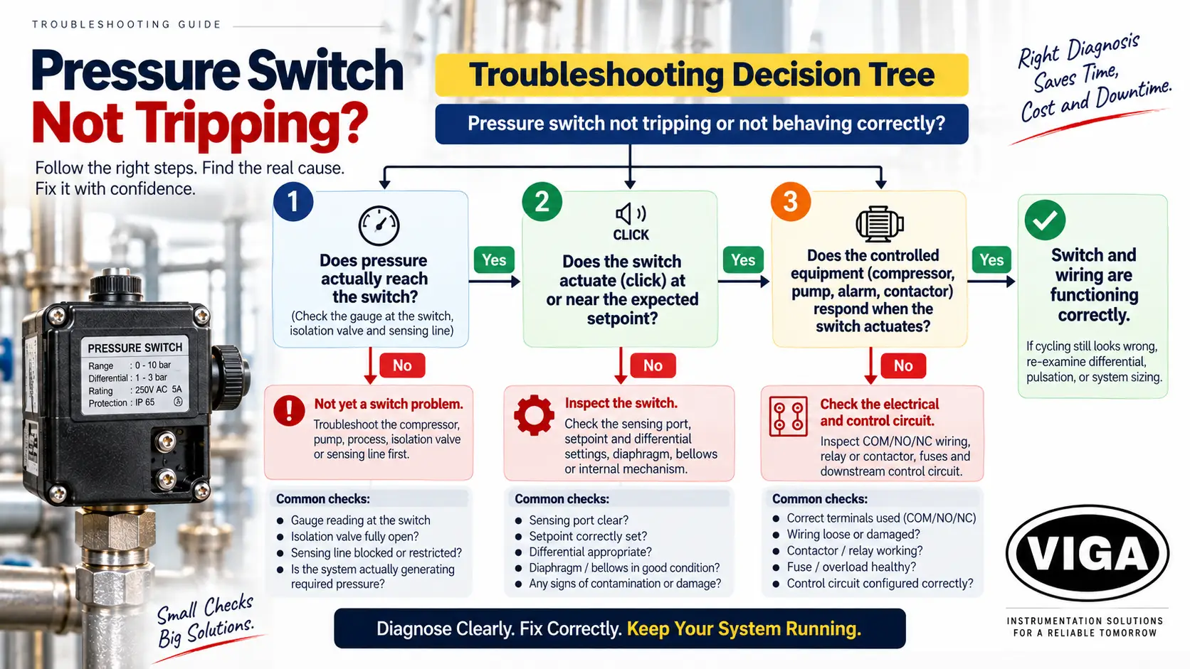
Troubleshooting Decision Tree
Pressure switch not tripping or not behaving correctly
Does pressure actually reach the switch?
Check the gauge at the switch, the isolation valve, and the sensing line.Does the switch actuate (click) at or near the expected setpoint?
Does the controlled equipment (compressor, pump, alarm, contactor) respond when the switch actuates?
A reading can be wrong while the gauge is entirely healthy. That is the point most troubleshooting misses.
The diagnostic sequence
Seven steps, in order. Stopping early is normal; most faults resolve by step five.
- Record what the gauge shows and what the plant expects, before anything is touched. A remembered value is not evidence.
- Ask what changed. A gauge that has read consistently for years and shifts over one weekend is more likely reporting a real process change than developing an internal fault on that schedule. New pump, altered valve position, fouled strainer, modified bypass, changed duty.
- Isolate and depressurise under the site procedure.
- Check zero. Where the design permits, vent the case as well. Note the pointer position and whether light tapping moves it.
- Compare against a calibrated reference gauge fitted at the same tapping point. Not a different branch of the same header.
- Characterise the error. Constant across the range, proportional to pressure, present only when hot, or intermittent? Each pattern points at a different group.
- Decide between recalibration, repair and replacement, using the framework near the end of this guide.
Diagnostic Decision Tree
Systematic Troubleshooting Workflow
Strictly adhere to plant and site-specific safety procedures.
- Zero shift or permanent set of element
- Worn or seized movement mechanism
- Pointer slip on spindle
Gauge rests normally. Proceed with dynamic reference checks.
- Blocked or restricted impulse line
- Closed or throttled root valve
- Siphon empty / unsealed
- Elevation head pressure discrepancy
- Genuine unmonitored process change
Instrument out-of-spec. Evaluate nature of deviation below.
- Span error
- Movement hysteresis
- Mechanical movement wear
- Internal calibration drift
- Zero offset error
- Reference/installation offset
- Missing static head correction
- Ambient temperature influence
- Process heat conducting through socket
- Direct solar radiation gain
- Case liquid fill viscosity changes
Thermal factors eliminated. Continue bench-level mechanical diagnosis and overhaul.
Pressure Switch Not Tripping: Troubleshoot in This Order
Confirm Actual Pressure at the Switch
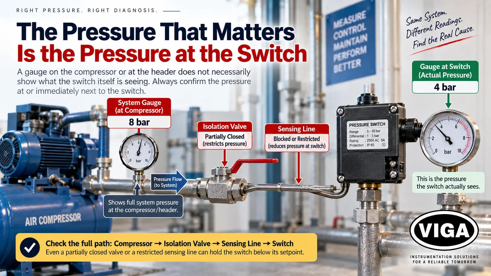
A gauge on the compressor or at the header does not necessarily show what the switch itself is seeing. Pressure drops across long pipe runs, undersized tubing, and partially open valves, so the reading that matters is the one at or immediately next to the switch, not upstream of it. Where no gauge is fitted directly at the switch, a portable test gauge screwed into an adjacent port for a few minutes settles the question. If the switch genuinely is not seeing the pressure the rest of the system shows, everything from here should focus on the path to the switch rather than the switch itself.
Inspect the Sensing Port
The sensing port is where the switch connects to the process, and contamination here is one of the more frequent reasons a switch will not trip. Compressed air carries compressor oil mist; water and steam lines carry scale; process fluids can leave residue behind. Over time this can restrict the narrow bore of the port and prevent pressure from reaching the diaphragm or bellows, without anything electrical being at fault.
Isolate power, then depressurize and isolate the process line before removing the switch (see Safety First above). Once removed, a visual check with a torch usually shows whether the bore is clear. How the port should be cleared, and whether it should be cleared at all rather than the unit replaced, depends on the model and material. The manufacturer’s maintenance instructions for that specific switch are the right reference rather than a general method, since an aggressive or incorrect cleaning approach can damage the bore or void a certification. On differential pressure switches there are two sensing ports, a high side and a low side, and both should be checked. A partly blocked port on only one side can produce an unstable or one-sided differential.
Check the Isolation Valve and Sensing Line
A clear port does not guarantee pressure is arriving in the first place. A root or isolation valve left even slightly closed after maintenance can throttle flow enough that a slow-building process falls short of setpoint, even though the same process would trip the switch quickly through a fully open valve. Trace the line back to its source and confirm every valve along the way is fully open, not just cracked. A snubber or restrictor fitted ahead of the switch to dampen pulsation can block in the same way as the port itself, and is easy to overlook while checking the port. On a switch mounted above its pressure source with a long vertical run of tubing in liquid service, trapped air can also hold the switch at a false reading; bleeding the line at the switch until liquid runs clean typically resolves this.
Verify Setpoint and Differential
Two separate settings govern how a pressure switch behaves. The setpoint (or range) is the pressure at which the switch changes state. The differential (also called the deadband, and sometimes discussed in terms of hysteresis) is the gap between the cut-in and cut-out points, and it determines how often the switch cycles. A correct setpoint paired with too narrow a differential produces chatter or short cycling; too wide a differential runs the connected equipment longer than intended.
Manufacturers commonly recommend keeping the working setpoint within the middle portion of a switch’s total range rather than at either extreme, since a switch operated near the top or bottom of its range tends to drift and wear faster. The exact recommended range, and the adjustment procedure itself, vary by model; this is covered in more detail in the Switzer and Indfos sections below. The current datasheet or manual for the specific model on the nameplate should be the final reference before changing any setting that affects shutdown or safety.
Check Electrical Contacts
If the switch clicks at the setpoint but the compressor, pump, or alarm does not respond, the sensing side is working and the remaining check is electrical. This is work for a qualified person following the site’s electrical safety procedure, with power correctly isolated before any terminal is touched. Loose screw terminals are a frequent culprit: vibration works them loose over time, and a loose connection can test continuous when static yet fail intermittently under load, which is why this is usually confirmed by a qualified technician monitoring a multimeter under controlled, isolated test conditions rather than by a visual check alone.
Most of these switches use a single-pole double-throw or single-pole change-over microswitch, with one common (COM) terminal, one normally-open (NO) contact, and one normally-closed (NC) contact. With power isolated, manually actuating the mechanism, where the design allows this safely, and checking continuity across the expected terminals shows whether the contact set itself is working. No continuity on either side, or continuity that stays closed on both, indicates a failed microswitch rather than a wiring problem. Separately, a switch wired to the wrong contact set for the application, or with the polarity reversed relative to what the control circuit expects, can appear permanently tripped even though it is working exactly as built. Checking the wiring diagram against the terminal actually in use rules out a wiring error before the switch itself is blamed.
Test the Switching Mechanism
Once the sensing path, the setpoint, and the wiring have all checked out, what remains is the mechanism that turns a moving bellows or diaphragm into a mechanical push against the microswitch lever. With the switch safely isolated and pressure applied gradually and under control, a working switch produces a distinct, single click at the setpoint. A soft or mushy trip, or one that needs progressively more pressure on repeated attempts, points to a mechanical issue: a range spring that has taken a permanent set, a stiff or contaminated pivot, or wear at the point where the sensing element contacts the microswitch plunger. Where the design allows it safely, pressing the actuating pin directly by hand, switch isolated and pressure removed, and checking continuity separates a mechanical sensing failure from an electrical one. A switch that clicks correctly under direct manual pressure but not under process pressure has a problem in the bellows or diaphragm, not the contacts.
Inspect for Corrosion, Moisture and Mechanical Damage
Enclosure ingress protection matters as much as the switch’s pressure rating. Humidity, condensation inside a sealed enclosure after a temperature swing, and dust or airborne contaminants all work against internal contacts over time, particularly where the installed IP rating is lower than the environment calls for. A white or green powdery deposit on the terminals is corrosion rather than dirt, and it raises contact resistance well before it causes a complete failure. That is often why a switch seems to work intermittently rather than failing cleanly. Light surface corrosion can sometimes be cleaned; contacts that are visibly pitted, or terminal threads that have been eaten into, call for replacement rather than cleaning.
The sensing element (a bellows or diaphragm, in materials that vary by model) can also fail on its own. A ruptured diaphragm typically shows as process fluid or moisture inside the electrical compartment, which is both a functional failure and, on a certified flameproof or weatherproof switch, a certification issue: the enclosure is no longer in its approved condition once opened or breached. A bellows that has lost its spring action after extended cycling tends to feel abnormally soft or fails to return fully to zero once pressure is released. Neither is a field repair.
Pressure Switch Symptoms and What They Usually Mean
Switch Clicks but Compressor Does Not Stop
The sensing side is working; the remaining fault is typically downstream: a burnt or welded contact inside the switch, a failed relay or contactor coil, a blown fuse in the control circuit, or wiring to the wrong contact set. Work through Check Electrical Contacts above, then trace the circuit from the switch terminal to the contactor coil.
Switch Trips Too Early
Either the setpoint has drifted low, or the switch is reading correctly while actual system pressure is lower than assumed. Check the gauge at the switch itself, not just the compressor gauge, before touching the setpoint. If the setpoint is confirmed correct and the switch still trips early and repeatedly, a fatigued range spring or a partially stuck mechanism is a likely cause.
Switch Trips Too Late
Check for a restricted sensing port or line first, since a partial blockage delays how quickly the switch feels a pressure rise even with a correct setpoint. If the sensing path is clear, the setpoint may simply be set higher than intended, or the switch may be operating near the top of its range, where accuracy typically degrades.
Switch Keeps Resetting
Short-cycling like this usually points to a differential set too narrow for the equipment being controlled. The connected pressure needs to swing through the full cut-in-to-cut-out gap before the next cycle should start, and a narrow differential lets normal pressure ripple cross it repeatedly. Where the model supports independent differential adjustment, widening it usually resolves this without touching the setpoint. If the differential is already correctly set, pulsation from a reciprocating compressor or a poppet valve can produce the same symptom.
Switch Works on Bench but Fails Installed
The switch itself is very likely fine. Look at the installation instead: a partly closed root valve, a blocked or kinked sensing line, a clogged snubber, vibration at the mounting point, or a sensing connection exposed to conditions the bench test did not reproduce.
Compressor Never Reaches Cut-Out
This may not be a pressure switch problem at all. If the compressor runs continuously without system pressure ever climbing to the switch’s setpoint, the switch may be reading correctly and simply never seeing the pressure it is waiting for. A worn valve plate, a leaking unloader, an undersized compressor for the load, or a leak elsewhere in the system can all produce this. Confirming the compressor can physically reach setpoint pressure, with a test gauge on the discharge line independent of the switch, is a useful check to run before the switch itself gets replaced.
Diagnostic Reference Table
Pressure Switch Diagnostics Reference
Systematic fault-isolation guide for switch testing, diagnosis, and resolution.
| Symptom | Likely Cause | First Test | What the Result Means | Next Action |
|---|---|---|---|---|
| Switch never trips even at full system pressure | Blocked sensing port, or isolation valve not fully open | Fit a test gauge at the switch body itself | Gauge reads low/zero → pressure isn't reaching the switch. Gauge matches system pressure → fault is inside the switch |
Clear the path to the switch first; only then investigate the switch mechanism |
| Switch trips well below the setpoint | Setpoint has drifted low, or the range spring has fatigued | Check the actual setpoint against a calibrated reference gauge | Setpoint confirmed correct against the reference but switch still trips early → mechanical fault | Reset against the reference gauge; replace if it drifts again quickly |
| Switch trips well above the setpoint | Setpoint has drifted high, or internal buildup is affecting the sensing element | Same calibrated-gauge check | Confirms whether the fault is the setting or the mechanism | Reset the setpoint; inspect the sensing element if resetting does not hold |
| Switch chatters or trips in rapid bursts | Differential set too narrow, or pressure pulsation at the sensing point | Widen the differential (where adjustable) and re-test | Chatter stops → differential was the cause. Chatter continues → suspect pulsation |
Fit or inspect a snubber if widening the differential does not resolve it |
| Switch clicks but the motor, solenoid or alarm does not respond | Failed contact inside the switch, or a fault downstream | Multimeter continuity check across COM/NO/NC while manually actuating the switch | Continuity behaves correctly → fault is downstream. No continuity or contacts stuck → switch has failed |
Trace the downstream control circuit, or replace the switch if the contacts have failed |
| No continuity across terminals under manual actuation | Microswitch has failed mechanically | Same continuity check, switch isolated from the circuit | Confirms an internal electrical failure | Replace the switch |
| Switch resets and re-trips within seconds | Differential too narrow for the connected equipment's recovery time | Check differential setting against normal cycle behaviour for that equipment | Differential narrower than the application needs | Widen the differential setting |
| Works on a bench test, fails once reinstalled | Sensing line, snubber, or a partly closed valve restricting flow in the actual installation | Compare bench performance against an in-line test gauge reading | Bench pass plus in-line fail → installation issue, not the switch | Trace and clear the full sensing path, not just the switch |
| Trip point shifts slightly on every cycle | Moisture or corrosion inside the terminal compartment | Open the terminal cover and inspect for deposits or discolouration | Visible corrosion confirms the cause | Clean and dry the enclosure if corrosion is light; check the IP rating against the environment; replace if contacts are pitted |
| Switch trips the instant power is connected, regardless of pressure | Wired to the wrong contact set (NC instead of NO), or reversed wiring | Check the wiring diagram against the terminal actually used | Confirms a wiring error rather than a switch fault | Correct the wiring to the terminal the control circuit expects |
| Switch worked fine until a recent process or pressure change | Switch range no longer matches the new operating pressure | Compare the nameplate range against the current process pressure | Confirms whether the switch is now undersized or oversized for the revised conditions | Replace with a switch rated for the current range; do not assume a like-for-like swap still fits |
| Two switches from the same batch behave differently at the same setting | Batch variation, a unit already drifting internally, or inconsistent installation between the two positions | Swap the two switches between positions and re-test | Fault follows the switch → that unit is faulty. Fault stays with the position → the installation there is the cause |
Replace the faulty unit, or recheck the wiring and sensing line at that position |
Switzer Pressure Switch Troubleshooting
Switzer Model Identification
Switzer’s mechanical range spans several series: the 200 series (021/023, 201/203/281, 204/208), the 300/DPS series for differential applications (301/303/304/381/384, DPS 301/303/361/363), and the 900 series (GH-901, GH-902, GH-903). All of them work on the same underlying principle, a bellows or diaphragm acting on a microswitch, so the general troubleshooting sequence above applies across the range. The model number on the nameplate identifies which series is fitted, and is the starting point for anything more specific than that.
What to Check Before Adjustment
Before touching a setpoint or differential screw, confirm the change is actually needed against a calibrated reference gauge rather than the switch’s own printed scale. Publicly available Switzer documentation describes that scale as an approximate reference rather than a calibration-grade reading, and notes that a setpoint can shift under changing static pressure or ambient temperature. A switch reading a percent or two off its printed number is not necessarily faulty.
Differential-Related Troubleshooting
Where the models genuinely differ is in how the differential is adjusted. Publicly available Switzer documentation describes the 201 as having a fixed, non-adjustable differential, while the 203 adds a separate adjustment that widens or narrows the differential without moving the setpoint, relevant where a switch is chattering but the trip point itself looks correct. The 281 is described as carrying two independent lever-and-microswitch assemblies from a single sensor, giving two setpoints off one pressure line. On the 300/DPS series, Switzer’s published literature describes the 301 and 361 as fixed-differential and the 303 and 363 as adjustable-differential variants of the same basic design.
Contact/Wiring Considerations
Electrical fault-finding on Switzer switches follows the general approach under Check Electrical Contacts above: identify the COM, NO and NC terminals from the wiring diagram for the specific model, and confirm continuity directly rather than inferring a contact arrangement from a similar-looking switch.
When the Exact Datasheet Is Required
Adjustment details, scale accuracy, contact arrangement, and whether a given differential is fixed or field-adjustable vary by exact model and range. Specifications vary by model and range; confirm the current datasheet for the exact part number before changing a setting, rather than treating every Switzer switch as if it adjusts the same way.
Indfos Pressure Switch Troubleshooting
Indfos Model Identification
Indfos’s PSM range includes PSM 520, PSM 550, PSM 630, and the refrigeration-duty PSM 690, alongside the DPSM differential series. All use the same bellows-and-microswitch principle as most mechanical pressure switches, so the general sequence above applies. The model number and range on the nameplate identify the specific variant fitted.
Differential and Enclosure Considerations
On the models where publicly available documentation confirms independent adjustment, widening the differential to address short-cycling does not move the setpoint, and vice versa; that distinction is worth having before a cycling problem gets treated as a wiring fault. Enclosure protection is not uniform across the PSM family either. Published product information shows ratings from around IP30 on some variants up to IP66 on others, which matters where a switch originally specified for a dry panel ends up mounted outdoors or on exposed equipment.
When the Exact Datasheet Is Required
Exact pressure range, differential range, contact configuration, and IP rating vary across the PSM family. Specifications vary by model and range; confirm the current Indfos datasheet for the specific model on the nameplate, rather than assuming a similar-looking unit shares the same rating.
Before Ordering a Replacement
Two switches can look identical and still be unsuitable replacements. Capturing the following from the failed unit, ideally with a clear photo of the nameplate, avoids matching by appearance alone:
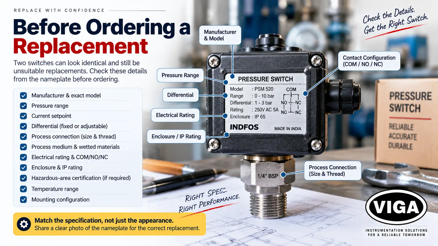
- Manufacturer and exact model — as printed on the nameplate, not inferred from appearance.
- Pressure range — the range the switch is built for.
- Current setpoint — where within that range it has been operating.
- Differential — fixed or adjustable, and the span it covers.
- Connection size and thread — plus orientation, if space around the switch is tight.
- Process medium — wetted materials suited to the process fluid, especially for corrosive, high-temperature, or refrigerant service.
- Electrical rating and COM/NO/NC configuration — voltage, current rating, and contact arrangement.
- Enclosure and IP rating — matched to the actual installation environment, not just the original spec if the environment has changed.
- Hazardous-area certification, if the application requires one — a flameproof or intrinsically safe switch needs a certified equivalent for the same zone and gas group; a general-purpose switch is not an acceptable substitute regardless of how similar it looks.
- Temperature range — ambient and process, since bellows and diaphragm materials have defined limits.
- Mounting configuration — panel-mounted, direct process-mounted, or remote-sensed via capillary.
Repair or Replace?
Usually adjustable or serviceable in the field:
- Setpoint drift, where the sensing element itself is intact
- Differential adjustment, on models that support it
- Loose or corroded terminals, where the contacts themselves are not pitted
- Installation-side issues, such as a blocked port, a partly closed valve, or a clogged snubber, that are not actually a fault with the switch at all
Usually replacement territory:
- A failed microswitch, confirmed by no continuity under direct manual actuation
- A ruptured diaphragm, or a bellows that has lost its spring action
- Contact surfaces that are visibly pitted rather than lightly tarnished
- A flameproof or weatherproof-certified enclosure that has been opened, damaged, or otherwise taken out of its certified condition
- A setpoint or differential that keeps drifting back after being reset, which points to a mechanical fault rather than a one-off adjustment issue
- Visible physical damage, or a terminal assembly with damaged insulation
Where a manufacturer’s own instructions specify repair limits, field-serviceable parts, or a mandatory replacement condition, those instructions take precedence over the general guidance above.
Illustrative Diagnostic Example
The scenario below is a generic, illustrative walkthrough of how the diagnostic sequence above applies in practice, not a specific VIGA service record.
Symptom: A compressor keeps running without ever cutting out, and the pressure switch is suspected of having failed.
Initial assumption: The switch has stopped tripping and needs replacement.
Test performed: A test gauge fitted directly at the switch body shows system pressure well below the switch’s setpoint, even though the compressor gauge appears to show normal pressure.
Finding: The isolation valve between the compressor line and the switch was only partially open. It looked open at a glance but was not fully so.
Fix: Opening the valve fully lets pressure reach the setpoint, and the switch trips normally.
Lesson: A switch cannot be judged faulty until the pressure it is actually receiving has been confirmed. That is why the “check these 3 things first” section comes before any work on the switch itself.
Frequently Asked Questions
Q1. Why is my pressure switch not tripping?
The first check is whether pressure actually reaches the switch at its sensing port; a switch cannot trip on pressure it never receives. If a test gauge at the switch confirms correct pressure is present and the switch still does not change state, the next things to check are the sensing port, the setpoint and differential settings, and the switching mechanism itself, in the order the decision tree above sets out.
Q2. Why does it trip and reset repeatedly?
Short-cycling like this usually points to a differential set too narrow for the equipment being controlled, letting normal pressure ripple cross the gap repeatedly. Widening the differential, on models where it is independently adjustable, often resolves it. Where the differential is already correctly set, pulsation from a reciprocating compressor or a poppet valve can produce the same symptom.
Q3. How do I test a pressure switch?
A test gauge fitted at or near the switch, combined with a multimeter connected across the load terminals, confirms whether the switch trips at the correct pressure and whether its contacts change state correctly, usually without removing it from the line. Manually actuating the mechanism, where the design allows this safely and with power isolated, separates a mechanical sensing fault from an electrical one.
Q4. Can a pressure switch be recalibrated?
Setpoint and differential drift can usually be corrected on site, against a calibrated reference gauge rather than the switch’s own printed scale. What recalibration cannot fix is damage to the sensing element itself. A bellows that has lost its spring tension, or a diaphragm with permanent deformation, will hold a new setting only briefly before drifting again.
Q5. How do I know if the pressure switch or the compressor is at fault?
If the compressor runs continuously without system pressure ever reaching the switch’s setpoint, the switch may be working correctly and simply never seeing the pressure it is waiting for. Confirming the compressor can physically reach setpoint pressure, with a test gauge on the discharge line independent of the switch, separates a compressor problem from a switch problem before either gets replaced.
Q6. Can it be tested without removing it from the line?
Usually, yes. A test gauge at a nearby port and a multimeter across the load terminals show whether the switch is responding to actual pressure without disconnecting the process piping. Full removal is typically only necessary once the fault has been narrowed to the mechanism itself.
Q7. When should the switch be replaced rather than repaired?
Once the fault is inside the sensing element or the microswitch (a ruptured diaphragm, a bellows that has lost its spring, contacts with no continuity under manual actuation, or visible pitting), field repair generally is not possible, and replacement is the appropriate step. A switch that keeps needing the same adjustment repeated over a short period is also typically signalling mechanical wear rather than a one-off setting issue.
Q8. How do I select the correct replacement?
Brand and general appearance are not enough. Matching the manufacturer, exact model, pressure range, differential range, process connection, electrical rating, contact configuration, and enclosure/IP rating, plus hazardous-area certification when the application calls for it, is what determines whether a replacement will actually work. A clear photo of the nameplate is usually the fastest way to confirm all of it at once.
Need a Replacement Pressure Switch?
Two switches can look identical and still be the wrong replacement. Model, range, differential, connection, and application all need to line up, not just the brand name. VIGA is an authorized distributor for Switzer, Indfos, WIKA, and the other instrumentation brands referenced in this guide, serving the Delhi NCR market.
Send a clear photo of the existing switch’s nameplate and connection, along with the application. These details make it easier to identify the correct replacement rather than matching by appearance alone.
- Switzer range: viga.in/products/instrumentation/switzer/
- Indfos range: viga.in/products/instrumentation/indfos/
- WIKA range (including PSD 4 and PSM 01 switches): viga.in/products/instrumentation/wika/
- Technical desk: +91-11-43025959 / +91-11-41582888
- Address: 20 Chawri Bazar, Delhi 110006