

Pressure Switch Not Tripping? Causes, Tests & Fixes
A pressure transmitter showing the wrong 4–20 mA output is usually reporting a fault somewhere in the loop, the process connection, or the receiver configuration — not confessing that its own sensor has died. Measure the loop current first. The value on the meter already narrows down which of four domains the fault lives in, and that single measurement prevents most unnecessary replacements.
The reliable order of work runs from the power supply and loop outward toward the sensor, with the transmitter itself treated as the last suspect, not the first.
Quick Diagnostic Table: What the Reading Can Tell You
The middle column matters as much as the first. A reading rules some causes in, but rarely proves any single one on its own.
| Observed current | What it can indicate | What it does NOT prove | Check first |
|---|---|---|---|
| 0 mA | Open loop, lost supply, blown fuse, tripped IS barrier, broken wire, failed AI channel | A dead transmitter | Continuity, supply, fuse, barrier, AI channel |
| ~3.6 mA (or device fault level) | Configured downscale failure signal, or a genuine low reading near LRV | Sensor failure — direction is set by config | Device diagnostics; impulse line; range |
| ~4 mA, process live | Process at/below LRV, blocked/isolated tapping, URV set too high | Sensor failure | Manifold/root valve; LRV/URV vs duty |
| ~8 mA (0–10 bar) | ~25% of span (≈2.5 bar) | Anything faulty | Compare to a reference pressure |
| ~12 mA (0–10 bar) | ~50% of span (≈5 bar) | A correct displayed value at the receiver | Reference pressure; then PLC/DCS scaling |
| ~16 mA (0–10 bar) | ~75% of span (≈7.5 bar) | Anything faulty | Compare to a reference pressure |
| ~20 mA, process normal | Process at URV, URV set too low, trapped/blocked high pressure | An over-pressure event | Reference pressure; range; blocked line |
| >20.5 mA | Over-range/saturation, or a fault region | A short circuit | Reference pressure; diagnostics |
| ~21–22 mA | Configured upscale failure signal, or wiring/insulation fault | A short circuit automatically | Diagnostics; insulation/resistance test |
| Fluctuating / noisy | Process pulsation, ground loop, shield issue, VFD/EMI | A failing sensor | Grounding scheme; cable routing; damping |
The Four Fault Domains
Almost every wrong-output problem belongs to one of four domains. Isolating the domain before choosing a test is the core of efficient troubleshooting.
- Transmitter — sensor failure, electronics failure, a diagnostics alarm, sensor/zero drift, diaphragm damage, or an output-stage fault.
- Loop — power supply, fuse, IS barrier, wiring, cable resistance, excessive load, insufficient terminal voltage, grounding, or EMI.
- Process — closed root valve, wrong manifold sequence, blocked or frozen impulse line, trapped pressure, wet-leg or seal/capillary problems, or a genuine over-pressure.
- Receiver (PLC/DCS) — incorrect analog-input scaling, wrong LRV/URV entered at the receiver, wrong engineering unit, wrong channel mapping, or a signal-conditioning error.
The current reading points toward a domain; the tests within each section below confirm the component.
Safety Before You Test
Loop diagnostics involve live electrical circuits and pressurised process connections. A series milliamp measurement must be made following the correct procedure for breaking into the loop; resistance or continuity functions must not be applied across an energised circuit. In hazardous areas, use the appropriate isolation and permit procedures, do not bypass intrinsic-safety barriers, and use only approved test equipment. Manifold and impulse-line work on a live or high-pressure system follows site isolation procedure. Site electrical/instrumentation procedures and the equipment manuals always take precedence over any general guidance here.
Pressure Transmitter Troubleshooting Decision Tree
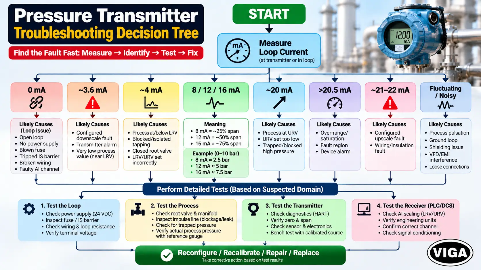
Measure loop current in series (mA)
Bench-test the transmitter only after field causes are eliminated.
Reconfigure / recalibrate / repair / replace according to the evidence.
What a 4–20 mA Signal Actually Tells You
A 4–20 mA transmitter represents pressure as a current. Two points are fixed by the range: 4 mA is the Lower Range Value (LRV, 0%) and 20 mA is the Upper Range Value (URV, 100%). The relationship is linear, which makes the expected output calculable and any error measurable.
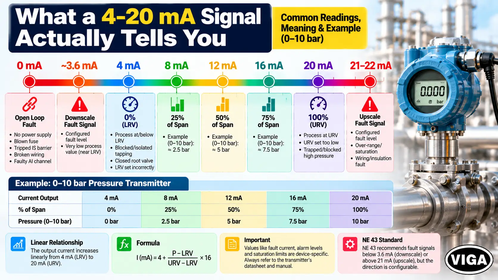
Current inside roughly 3.8–20.5 mA is treated as measurement information. Current below or above that window is generally either saturation (the process pushed slightly past range) or a device signalling a fault. The essential mental model: the current value narrows the fault domain; it does not, by itself, identify the failed component. A clean 4 mA can be a correct reading at LRV or a blocked tapping. A clean 20 mA can be a correct reading at URV or a trapped pressure. Only pairing the reading with a reference pressure and the device diagnostics turns a value into a diagnosis.
The NE 43 qualification
The NAMUR NE 43 recommendation gives the process industry a common framework for failure signalling on a 4–20 mA loop. In broad terms it reserves roughly 3.8–20.5 mA for valid measurement and treats current at or below about 3.6 mA, or at or above about 21 mA, as a device fault rather than a reading. Many European and Japanese manufacturers implement it.
Three qualifications matter in the field:
- NE 43 is a recommendation, not a universal law. Not every transmitter implements identical bands, and some legacy or non-compliant devices behave differently.
- The failure direction is often user-configurable. A smart transmitter can commonly be set to drive its output downscale (~3.6 mA) or upscale (~21 mA) on an internal fault, so 3.6 versus 21 reflects a configuration choice as much as a fault type.
- Saturation and failure are different states. A signal at 20.5 mA may be a genuine over-range measurement; 21–22 mA is more likely a failure signal. Confirm which the device is actually producing.
Sensor, transmitter, transducer — a quick clarification
Commercial content often uses these terms interchangeably, but industrial products differ. A pressure sensor or transducer commonly refers to the sensing element or a device with a raw or low-level output; a pressure transmitter conditions that signal into a standardised output — typically 4–20 mA, frequently with HART — and is often a 2-wire loop-powered device. In practice they can differ in output type, power requirement, signal conditioning, communication and installation, so match documentation to the exact device rather than the generic term.
Transmitter architecture: why the wiring type matters
The loop-voltage discussion in this article applies primarily to conventional 2-wire loop-powered transmitters, where power and signal share the same pair and the device operates on the current it draws. 3-wire and 4-wire transmitters take separate power and drive the output differently, so a 2-wire loop-budget calculation should not be applied blindly to them. Confirm the wiring type before using the voltage-budget math below.
Pressure Transmitter Reads 0 mA
Zero current is not a measurement, and on its own it does not prove the transmitter has failed. It means the loop is open — current cannot flow at all — so it is a Loop-domain problem until proven otherwise. Confirm the supply is energised and at its nominal DC value, check the loop fuse and any IS barrier, inspect field wiring for a break or a loose/corroded terminal, and confirm the DCS/PLC analog-input channel is healthy and correctly assigned.
To split the loop quickly, inject a known current (for example 12 mA) with a loop calibrator at the field terminals. If the control system then reads 12 mA, the wiring and input card are sound and the transmitter is the suspect; if not, the break lies between the injection point and the input card.
~3.6 mA / Fault-Current Troubleshooting
A reading pinned at a clean, low fault level (around 3.6 mA on many devices) usually means the transmitter is driving a downscale failure signal because its self-diagnostics flagged an internal problem. Read the device diagnostics to confirm, rather than assuming — the same value can appear for other reasons on some models, and the downscale direction may itself be a configured choice. Before treating it as a failed sensor, rule out a blocked or isolated impulse line and a range set so that the real pressure sits below LRV.
Pressure Transmitter Stuck at 4 mA
A genuine ~4 mA with the process live can simply mean the pressure the transmitter sees is at or below LRV. The ordinary causes to clear first are process-side and configuration: a closed root valve or a manifold in the wrong sequence isolates the sensor at zero; a blocked impulse line holds it low; and a URV set far above the operating pressure collapses a real reading toward 4 mA and imitates a failure. A persistent low output points back to the sensor only after the process path and range are verified.
8, 12 and 16 mA: Calculating the Expected Pressure
Mid-scale values are not faults in themselves — they are just points on the line. Converting current back to pressure (the receiver’s job) uses the inverse of the range formula:
For a 0–10 bar transmitter:
| Output | Pressure |
|---|---|
| 4 mA | 0 bar |
| 8 mA | 2.5 bar |
| 12 mA | 5.0 bar |
| 16 mA | 7.5 bar |
| 20 mA | 10 bar |
If the measured current matches the reference pressure through this formula but the displayed value does not, the transmitter is doing its job and the fault has moved to the receiver — covered below.
Pressure Transmitter Stuck at 20 mA
A reading near a valid 20 mA can be entirely correct if the process is at URV, so confirm actual pressure against a reference before treating it as a fault. If the process is normal but the output still parks high, look for a URV set too low for the duty, or a trapped/blocked line holding elevated pressure after a spike. Re-ranging to the real operating window, or clearing the blocked path, resolves most of these without opening the device.
Above 20 mA / Alarm-Current Troubleshooting
Output above roughly 20.5 mA — often clamped near 22 mA — should not be assumed to mean a short circuit. It can be a configured upscale failure signal (read the fault code with a communicator), a wiring or insulation fault such as moisture bridging terminals in a field junction box (an insulation test to earth and a loop-resistance check separate this from a device fault), or a protection/over-range response defined by the device documentation. Because the reading spans a near-normal saturation value, a genuine device alarm, and an electrical fault, the value alone is not a diagnosis.
Fluctuating or Noisy Output
An output that jumps or carries a visible ripple usually points at the installation or the process, not the sensing element. Genuine process pulsation (near pumps or reciprocating equipment) is real and is best addressed with output damping suited to the loop’s response needs. Electrical noise comes mainly from two sources. A ground loop — multiple ground points on shield or signal, or a shield bonded at both ends — lets circulating current ride on the measurement; a common, effective practice is bonding the shield at one end only, typically at the control-system end, though the correct scheme is subordinate to the plant grounding architecture, manufacturer instructions and hazardous-area rules. EMI from VFDs and motors couples onto signal cable running parallel to power cable; route instrument cable in a separate tray, cross power cables at 90° where unavoidable, and use twisted shielded pair. On a HART loop the same noise degrades digital communication, so a clean analog signal and reliable HART comms tend to arrive together.
Slow Response and Pressure Drift
Drift is the quiet failure: the loop looks healthy and the number looks plausible, but it has walked away from the true pressure. Confirm it against a reference gauge or a deadweight tester first, because a “drift” that is really a wrong range or a process restriction needs a different fix. Two genuine mechanisms: calibration drift shows a repeatable, predictable zero or span offset while the device still tracks pressure changes correctly, and is a trim job; diaphragm or seal damage — lost fill fluid, a clogged or kinked capillary, a corroded wetted diaphragm — produces drift and sluggish response that recalibration cannot hold, and needs a seal rebuild or replacement.
Loop Power and Voltage-Budget Troubleshooting
Voltage starvation is one of the most under-diagnosed causes of a wrong reading, because it appears only at high output. A 2-wire loop-powered transmitter needs a minimum voltage across its terminals to operate, and that voltage is lowest at 20 mA, where the drop across loop resistance is greatest.
R(total) is every series element: field wiring, the sense/load resistor (commonly 250 Ω where HART is used), any IS barrier, and series indicators or isolators.
Worked example (illustrative — verify against your device): 24 V DC supply; R(total) = 250 Ω load + 100 Ω barrier + 50 Ω wiring = 400 Ω, at 20 mA.
- Voltage drop = 0.020 × 400 = 8 V.
- Terminal voltage ≈ 24 − 8 = 16 V.
If the installed transmitter needs more than the available terminal voltage at 20 mA, the loop is under-budgeted. The minimum terminal (lift-off) voltage is model-specific — read it from the datasheet; do not assume a fixed figure such as 12 V applies to every device. Always measure voltage at the transmitter terminals under 20 mA load, not at the panel, and confirm the supply is stable under load, since a shared supply can sag as devices switch.
Process, Manifold and Impulse-Line Checks
Before any calibration or replacement, confirm the sensor is actually seeing the process — a large share of “faulty transmitter” reports are process-side isolation. Verify the root/isolation valve is open and the manifold is in the correct measuring sequence (for a DP application, block valves open and the equalising valve closed). Check impulse lines for blockage, plugging, freezing, or trapped gas/liquid legs that hold a false pressure, and on wet-leg or remote-seal systems confirm fill and leg integrity. The exact valve arrangement differs between gauge, absolute and differential-pressure applications, and live/high-pressure manipulation follows site isolation procedure.
LRV, URV and Transmitter Configuration
A wrong reading is not always a calibration problem — it is often a configuration mismatch. Keep these operations distinct, because they are not interchangeable: re-ranging changes the LRV/URV that define 4 mA and 20 mA and is a configuration change, not a calibration; verification applies known reference pressures and compares output without changing anything; a zero trim corrects a zero offset; a sensor trim corrects the pressure reading across the range; and an output (D/A) trim corrects the 4 mA and 20 mA output points against a reference milliamp meter. Confirm LRV/URV match the duty before assuming a sensor trim is needed.
When the Transmitter Is Correct but the PLC/DCS Shows the Wrong Pressure
A correct 4–20 mA current does not guarantee a correct displayed value. The transmitter can be healthy and accurate while the receiver converts the current to the wrong engineering value — a Receiver-domain fault that no amount of transmitter replacement will fix.
The receiver applies the inverse range formula, using the LRV, URV and unit entered in its analog-input block. If any of those entries is wrong, the current is right and the number is wrong.
Illustrative example (not a real field case):
- Transmitter range: 0–10 bar. Reference pressure: 5 bar. Expected output: 12 mA. Measured output: 12.01 mA.
- DCS display: 7.5 bar.
The measured current (12.01 mA) is correct for 5 bar, so the transmitter is fine. The displayed 7.5 bar indicates receiver-side scaling. For instance, if the URV in the DCS analog-input block was entered as 15 bar instead of 10 bar, 12 mA scales to (12 − 4)/16 × 15 = 7.5 bar — exactly the wrong value shown. The fix is in the DCS configuration, not the field.
What to check on the receiver side: the LRV and URV entered at the AI block, the engineering unit, the channel assignment, the input mode (current vs voltage), and any signal conditioning or square-root extraction left enabled by mistake. This section answers a common and often-missed situation: the field is right, the screen is wrong.
HART Troubleshooting
HART overlays digital communication on the analog loop, so a communicator can read the device’s diagnostics, configuration and trim status without breaking the loop — frequently the fastest way to see the specific fault behind an alarm current.
HART needs adequate loop resistance so the digital signal can develop a detectable voltage. The specification defines the loop resistor in the range of roughly 230–600 Ω, with 250 Ω most commonly used because it also converts 4–20 mA to a 1–5 V range. Many modern PLC/DCS analog-input cards and isolators already provide this load internally; a bare loop with only a low-impedance receiver may not, and a resistor must then be added. Confirm the actual requirement against the device and host documentation rather than treating 250 Ω as an unconditional rule. If communication fails, check for a supply too low to carry the added resistance at 20 mA, excessive EMI corrupting the FSK signal, and a communicator loaded with the correct device description and HART revision.
How to Bench-Test a Pressure Transmitter
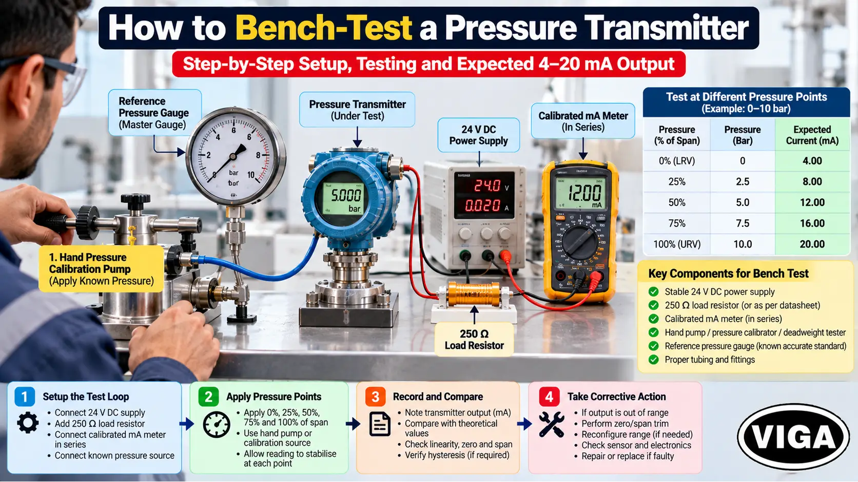
A bench test confirms whether the device itself is healthy, independent of the field loop. Power it from a stable DC supply appropriate to the device, place a suitable load in series (250 Ω is typical and enables HART on the bench), and connect a calibrated milliamp meter in series. Apply known reference pressures with a hand pump plus a master gauge, or a deadweight tester, and step through 0%, 25%, 50%, 75% and 100% of range. For a 0–10 bar device that is 4, 8, 12, 16 and 20 mA — but the acceptable deviation must come from the transmitter’s published accuracy specification, not an assumption of exact values. Linear, repeatable, in-tolerance output clears the device; unstable or non-linear output confirms it.
Reconfigure, Recalibrate, Repair or Replace?
| Situation | Correct action |
|---|---|
| Reading correct but 4/20 mA points don’t match the duty | Reconfigure (re-range LRV/URV) |
| Displayed value wrong but current correct for the reference | Fix receiver (PLC/DCS) scaling |
| Stable, repeatable offset; device still tracks changes | Recalibrate (verify, then trim) |
| 4/20 mA output points off vs a reference mA meter | Output (D/A) trim |
| Damaged capillary, lost seal fill, corroded diaphragm | Repair/replace seal system |
| Erratic, non-repeatable, drops in and out | Replace |
| Diagnostics hold a fault after process + wiring cleared | Replace |
| Fails bench test | Replace |
Common Troubleshooting Mistakes
- Replacing the transmitter before measuring the actual loop current.
- Measuring supply voltage at the panel instead of terminal voltage at the device under 20 mA load.
- Reading 0 mA as a dead transmitter when it almost always means an open loop.
- Assuming any value above 20 mA is a short circuit, ignoring over-range and configured upscale failure.
- Replacing a healthy transmitter when the fault is receiver-side scaling.
- Overlooking a closed root valve or a manifold left in the wrong sequence.
- Ignoring the configured fail-safe direction when reading 3.6 mA versus 21 mA.
- Blaming calibration before verifying LRV/URV against the real duty.
- Bonding the cable shield at both ends and creating a ground loop.
- Performing a zero trim to mask a process-side or seal problem instead of finding the cause.
When a Replacement Transmitter Is Actually Justified
Replacement is justified once the loop, supply, process path, receiver configuration and calibration are cleared and the device still fails — an erratic output, a persistent diagnostics fault, physical seal or diaphragm damage, or a failed bench test. Choosing a like-for-like replacement blindly can reintroduce the same fault, so match the specification to the application.
| Parameter | Confirm |
|---|---|
| Pressure type & range | Gauge / absolute / differential; span suited to the duty |
| LRV / URV | Set to the real operating window with sensible margin |
| Accuracy class | Meets the loop requirement |
| Output & protocol | 4–20 mA, HART revision if required |
| Process connection | Thread/flange size and standard match |
| Wetted materials | Compatible with the medium |
| Process temperature | Within device limits; seal/capillary if hot |
| Diaphragm seal | For viscous, hot, crystallising or slurry media |
| Hazardous-area certification | Correct Ex rating and IS parameters for the zone |
| Ingress protection | IP rating suited to the environment |
| Mounting & electrical entry | Fits the installation and cable gland |
For a specification-matched replacement, VIGA (Vinod Gautam Sales), based in Delhi and serving the wider NCR industrial market, is an Authorized Distributor of WIKA and Mass pressure transmitters and can help confirm range, output, process connection and materials against an existing loop. See the WIKA pressure transmitter range, the Mass pressure transmitter range, or reach the technical desk to match a replacement to the application.
Technical FAQ
Q1. Why is a pressure transmitter stuck at 4 mA?
A clean, configured low level (around 3.6 mA) usually signals a downscale device fault; a genuine 4 mA with the process live usually means a blocked or isolated impulse line, a closed manifold valve, or a URV set above the operating pressure. Verify the process path and range before assuming the sensor failed.
Q2. Why does a pressure transmitter read 0 mA?
Zero current means the loop is open, not that the transmitter is dead. Check supply, fuse, IS barrier, wiring continuity and the analog-input channel. Injecting a known current at the field terminals confirms the wiring and input card independently.
Q3. Why does a pressure transmitter read 20 mA?
It can be correct if the process is at the upper range value. If the process is normal, suspect a URV set too low or a trapped/blocked line holding pressure. Confirm actual pressure against a reference first.
Q4. Why does a pressure transmitter output 22 mA?
Around 22 mA is usually a configured upscale failure signal or an electrical fault (moisture or insulation breakdown in the loop), not automatically a short circuit. Read the device diagnostics and run an insulation/resistance check.
Q5. What causes a fluctuating 4–20 mA signal?
Real process pulsation, or electrical noise from a ground loop, a shield bonded at both ends, or VFD/motor EMI. Address damping for pulsation; for noise, use single-point shield grounding (subject to plant and Ex rules), separate signal from power cable, and use twisted shielded pair.
Q6. How do you test a pressure transmitter?
On the bench, power it through a load resistor (250 Ω is typical), put a calibrated mA meter in series, apply known reference pressures with a hand pump and master gauge or a deadweight tester, and step through 0–100% of range. Tolerance comes from the device’s accuracy spec.
Q7. How do you calibrate a 4–20 mA pressure transmitter?
Verify first — apply reference pressures and compare output. If correction is needed, apply the right operation: zero trim, sensor trim, or output/D-A trim. Re-ranging LRV/URV is a configuration change, not a calibration.
Q8. What causes pressure transmitter drift?
A repeatable offset while the device still tracks changes is calibration drift, correctable by trimming. Drift that recalibration will not hold, often with sluggish response, points to a diaphragm-seal problem such as lost fill fluid or a clogged capillary.
Q9. Why is the transmitter correct but the PLC/DCS pressure wrong?
The receiver is scaling the correct current to the wrong engineering value — usually a wrong LRV/URV or unit entered in the analog-input block, a wrong channel, or leftover signal conditioning. Verify the current against a reference, then fix the receiver configuration.
Q10. How does HART troubleshooting work?
A communicator reads the device’s diagnostics and configuration over the loop. It needs adequate loop resistance (typically at least ~230–250 Ω; often provided by the PLC/DCS card), a noise-free pair, and the correct device description and HART revision.
Q11. What voltage should be available at a loop-powered transmitter?
Enough to keep the terminal voltage above the device’s minimum (lift-off) voltage at 20 mA, where the loop drop is highest. The exact figure is model-specific — read it from the datasheet.
Q12. What is the difference between re-ranging and calibration?
Re-ranging changes which pressures correspond to 4 mA and 20 mA and needs no reference pressure on most smart devices. Calibration verifies and, if needed, trims the device’s accuracy against an applied reference. Re-ranging is configuration; calibration is metrology.