

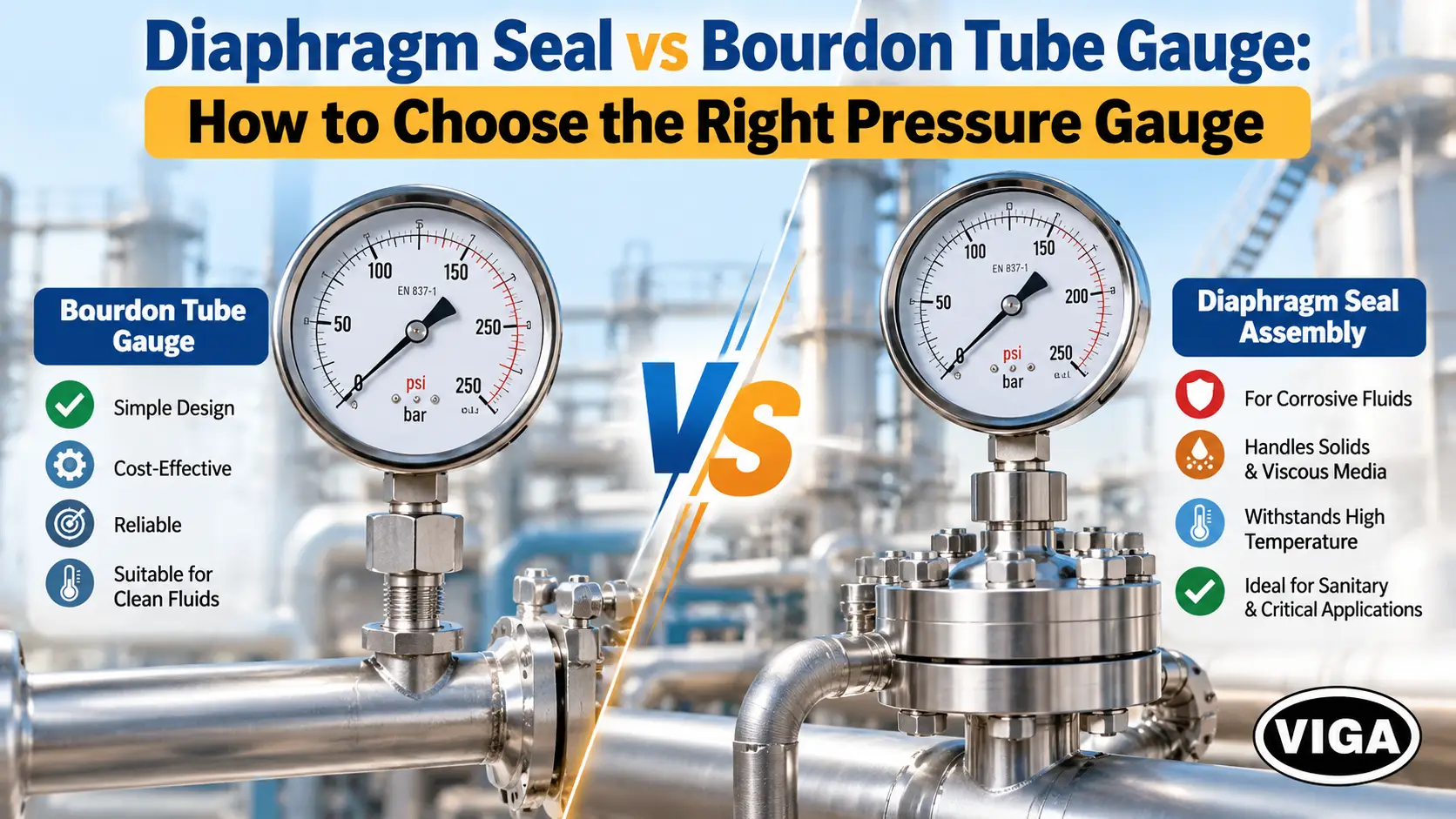
Diaphragm Seal vs Bourdon Tube Gauge: How to Choose
Diaphragm Seal vs Bourdon Tube Gauge: How to Choose the Right Pressure Gauge
A Bourdon tube gauge does its job well for as long as the process fluid can sit inside a thin, dead-ended metal tube without attacking it, blocking it or solidifying in it. Once any of those things happens, the gauge either fails outright or, worse, keeps showing a believable number that no longer reflects line pressure. A diaphragm seal removes the fluid from the gauge entirely: a membrane takes the process pressure, and a sealed fill fluid carries it to the Bourdon tube. That protection costs money, adds some error and changes how the instrument is maintained, so it belongs only where the process genuinely demands it.
The 3-Second Elimination Rule
Pressure Gauge Selection Criteria
Technical reference guide for gauge selection based on media and operational conditions
| Choose | When | |
|---|---|---|
| Rule 1 | Direct Bourdon gauge | Fluid is a clean gas or liquid, carries no solids, stays freely flowing at the coldest temperature the line reaches, is compatible with the wetted material (copper alloy or 316L), and medium temperature sits inside the gauge datasheet limit (typically +60 °C for copper-alloy gauges, +200 °C for unfilled stainless gauges, +100 °C for liquid-filled stainless gauges) |
| Rule 2 | Diaphragm seal assembly | Fluid attacks 316L or copper alloy at its real concentration and temperature; carries solids or fibres; thickens, cures or crystallises on cooling or standing; needs a cleanable, crevice-free sanitary connection (3-A or EHEDG where required); needs exotic wetted materials such as Hastelloy C276, tantalum or PTFE; or runs hotter than the gauge can take |
| Rule 3 | Neither: fix the real cause | The problem is reciprocating-pump pulsation, mechanical vibration, steam, or overpressure spikes. Specify a snubber or restrictor, a liquid-filled case, a siphon, or a gauge saver. A diaphragm seal is not designed to cure any of these |
The temperature figures above come from WIKA’s published datasheets for its standard copper-alloy (model 111.10) and stainless steel (models 232.50 and 233.50) Bourdon gauges. Other manufacturers and models differ, so the datasheet of the gauge actually being installed governs.
Decision Flowchart
Pressure Instrumentation Selection Logic
Failure diagnosis and diaphragm seal specification decision tree
What is actually failing?
Pulsation / vibration / steam / overpressure?
No seal needed.
Clean, solids-free, flows freely when cold, compatible with 316L or copper alloy?
Medium within gauge datasheet limit?
- ≤100 °C filled SS
- ≤200 °C unfilled SS
- ≤60 °C copper alloy
For steam, a siphon usually brings a direct gauge back inside its limits before a seal is ever needed. The ~100 °C mounting threshold follows WIKA’s diaphragm seal selection guidance.
Direct Bourdon vs Diaphragm Seal at a Glance
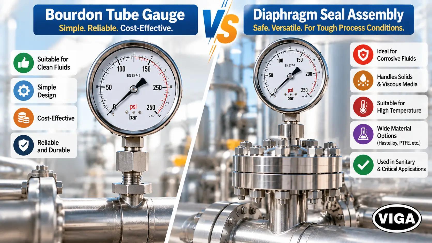
Technical Comparison: Direct Bourdon vs. Diaphragm Seal
Comprehensive evaluation of wetted parts, media compatibility, maintenance, and overall performance
| Factor |
Standard
Direct Bourdon gauge
|
Protected
Bourdon gauge + diaphragm seal
|
|---|---|---|
| Wetted parts | Bourdon tube, socket | Diaphragm, lower housing |
| Suited to | Clean, compatible fluids | Corrosive, plugging, viscous, crystallising, hygienic, hot |
| Wetted material range | Copper alloy, 316L, Monel | Adds Hastelloy, tantalum, titanium, PTFE coatings and more |
| Plugging resistance | Poor with solids | Good with flush or in-line designs |
| Accuracy | Gauge class only | Gauge class plus seal effects |
| Response | Immediate | Slower with long capillaries or cold, viscous fill |
| Field swap | Minutes, behind an isolation valve | Assembly replaced or workshop-refilled |
| Upfront cost | Low | Several times higher |
Where a Direct Bourdon Gauge Belongs
The Bourdon tube is a curved tube of flattened, oval section, closed at its tip. Internal pressure pushes the oval towards round, the curve opens slightly, and a link, segment and pinion convert that small tip movement into pointer travel. EN 837-1 governs these gauges in Europe, covering nominal sizes from 40 to 250 mm and ranges up to 1,600 bar; ASME B40.100 is the corresponding US reference.
On compressed air, clean water, hydraulic oil, lube oil and siphon-protected steam, nothing competes with it on cost, simplicity or reliability. Specifying a seal on these services buys nothing except extra error and a harder maintenance job.
Temperature is where direct mounting runs out first. WIKA’s own datasheets make the limits concrete:
Operating Temperature Limits
Maximum medium and ambient temperature ratings by gauge construction
| Gauge construction (WIKA example) | Max. medium temperature | Ambient |
|---|---|---|
|
Copper-alloy wetted parts, model 111.10
|
+60 °C | −40 to +60 °C |
|
Stainless steel, unfilled, model 232.50
|
+200 °C | −40 to +60 °C |
|
Stainless steel, glycerine-filled, model 233.50
|
+100 °C | −20 to +60 °C |
Two points often get confused here. The +60 °C figure attached to glycerine-filled gauges is the ambient limit; the medium limit for the filled stainless model is +100 °C. And every Bourdon gauge carries its own temperature effect: WIKA specifies up to ±0.4 % of span for every 10 K away from the +20 °C reference, before any seal is added.
For steam, a siphon forms a condensate barrier so the gauge sees water at close to ambient temperature rather than live steam. For hot liquids and vapours above roughly 100 °C that a siphon cannot handle, WIKA’s diaphragm seal guidance calls for a cooling element or capillary.
The weak point, though, is not temperature. It is geometry. The Bourdon tube is dead-ended. Fluid goes in and stays there, undisturbed, through every shutdown, every cool-down and every change of batch. Every failure described below grows out of that stagnant pocket.
Media That Justify a Diaphragm Seal
Corrosive media
A corrosive fluid does not automatically mean a seal. If 316L or Monel wetted parts are proven compatible at the actual concentration and temperature, a direct stainless gauge is the correct, cheaper answer. The seal becomes necessary when no economical tube alloy survives, or when a leak at the gauge would release a hazardous chemical. The reason is simple: a seal only needs the diaphragm and lower housing in exotic material, while a direct gauge would need the whole thin-walled tube made from it.
Watch the tube wall. It is thin because it has to flex, so corrosion that would take years to penetrate a pipe can breach a Bourdon tube far sooner. The warning sign is gradual reading drift as the wall thins and the tube’s stiffness changes, well before any visible leak.
Viscous and sticky media
Manufacturers do not publish a single viscosity number above which a seal becomes mandatory; WIKA, Kobold and others simply list “highly viscous” media among the services seals are built for. The practical test is behaviour at the coldest temperature the line will see, not at design temperature. A fluid that pours freely at 60 °C but has to be heated to be pumped at 15 °C will fill a Bourdon bore during a shutdown and set there.
Resins, adhesives, inks, paints, heavy fuel oil, bitumen and glucose syrups belong in this group. The answer is a large, flush diaphragm with no cavity for the fluid to travel into. Where the medium solidifies at ambient temperature, the seal is heat-traced along with the line.
Slurry, sludge and suspended solids
Solids settle in the Bourdon tube and in the small cavity of a threaded seal alike. For moderate solids, a flush-diaphragm or in-line seal is the starting point, and a flushing ring lets the diaphragm face be rinsed through side ports without disturbing the filled system.
For thick sludge and fibrous waste streams, an isolation ring usually outperforms any diaphragm seal. It clamps between two pipe flanges and senses pressure through a flexible full-bore sleeve, so there is no cavity at all. Ashcroft positions isolation rings for water, wastewater and mining service at lower pressures, noting that their material choice is narrower than that of diaphragm seals.
Crystallising and polymerising media
Here the numbers are unforgiving. Commercial 50 % caustic soda solidifies at about +12 °C, and producers note it becomes difficult to pump once it drops to around +15 °C. A 40 % solution solidifies at about +15 °C. In any unheated plant that sees a cold night, that solution will crystallise inside a Bourdon tube during a shutdown. Brines, sugar solutions and some salt solutions behave similarly, and monomers can polymerise in a stagnant pocket.
A flush seal minimises the stagnant volume, and heat tracing keeps the seal face above the solidification point.
Sanitary and hygienic processes
A dead-ended coil cannot be cleaned in place, and product residue in it can harbour contamination. Sanitary service calls for a flush, polished, crevice-free diaphragm on a hygienic clamp or dairy fitting, compatible with CIP and SIP cycles. The fill fluid must be food-grade, because a ruptured diaphragm puts it straight into the product. WIKA’s assembled sanitary seals, for instance, list FDA-approved glycerine for non-vacuum service and FDA-approved mineral oil for vacuum service. Where 3-A or EHEDG compliance is required, confirm it on the seal documentation, not the catalogue cover.
High-temperature and hazardous media
Above the gauge’s datasheet limit, a seal with a cooling element or capillary moves the gauge away from the heat. The system’s upper limit is then set by the diaphragm joining method, the fill fluid and the instrument together, per WIKA’s flange seal datasheets.
With toxic or flammable media, the argument is consequence. An all-welded seal keeps the thin tube out of the process and removes potential leak paths. It does not replace a hazard review, and the seal body, gasket and connection still need a pressure and material rating for the service.
When a Seal Will Not Fix the Problem
Pressure Gauge Troubleshooting Matrix
Root-cause failure diagnosis and recommended corrective actions
| SYMPTOM | ACTUAL CAUSE | CORRECT FIX |
|---|---|---|
|
Pointer flutter, worn movement teeth
|
Pump or compressor pulsation |
SOLUTION
Snubber or restrictor, plus liquid-filled case
|
|
Pointer shake, broken movement
|
Mechanical vibration |
SOLUTION
Liquid-filled gauge; better support or remote mounting
|
|
Fogged window, damaged dial
|
Live steam at the gauge |
SOLUTION
Siphon, primed before commissioning
|
|
Bent pointer, zero shift after spikes
|
Overpressure |
SOLUTION
Gauge saver or pressure limiter; re-select range
|
|
Nothing failing, clean fluid
|
None |
DIRECT SPEC
Direct Bourdon gauge
|
WIKA’s own datasheet for its liquid-filled stainless gauge pairs the filled case with a restrictor for strong pulsation. That combination is the standard answer on hydraulic systems.
One trap: on dirty service, a snubber’s small orifice plugs just as readily as a Bourdon tube. Where solids and pulsation occur on the same line, the two problems have to be solved together, not one accessory at a time.
Read the Failed Gauge Before Choosing Its Replacement
The removed instrument is the best process data available. Open it, look at the socket, and match what you see:
Removed Gauge Inspection Guide
Physical inspection findings, failure mechanisms, verification checks, and engineering modifications
| Observed on the removed gauge | Likely mechanism | Check | Likely modification |
|---|---|---|---|
|
Packed socket, sediment in bore
|
Solids settling in dead-ended tube | Solids content and size |
Flush or in-line seal; isolation ring for sludge
|
|
White crystalline deposit
|
Crystallisation during cool-down | Concentration, lowest line temperature |
Flush seal with heat tracing
|
|
Pointer stuck at a normal-looking value
|
Bore blocked while pressurised | Compare with a test gauge |
Plug-resistant seal
|
|
Pointer lags pressure changes
|
High viscosity in bore | Viscosity at lowest temperature |
Large flush diaphragm
|
|
Slow drift over weeks, then leak
|
Tube wall thinning | Tube material vs medium |
Compatible wetted material, or seal
|
|
Pitting or discolouration at socket
|
Chemical attack | Concentration, temperature, contaminants |
Material review; seal if no economic alloy
|
|
Fogged window, darkened dial
|
Excess heat | Medium temperature at the gauge |
Siphon for steam; seal with cooler or capillary
|
|
Broken teeth, loose pointer
|
Pulsation or vibration | Pump type, mounting |
Snubber, liquid fill, support
|
The stuck-at-normal gauge deserves the most attention. A gauge that reads zero gets replaced within the shift. A gauge frozen at a plausible value gets trusted.
How a Diaphragm Seal Works
The seal places a thin membrane between process and instrument. Everything above the membrane, including the Bourdon tube and any capillary, is evacuated and completely filled with a system fill fluid, then sealed. Process pressure deflects the diaphragm, which displaces fill fluid into the Bourdon tube, and the gauge responds as though it were measuring directly.
Two physical constraints drive seal sizing.
Displacement volume. The Bourdon tube needs a certain volume of fluid pushed into it to travel full scale. WIKA’s selection guidance states that the seal’s available displacement must exceed what the measuring element needs. A small diaphragm on a low range runs short of stroke, and the diaphragm’s own stiffness starts to eat into the reading. That is why low ranges need larger diaphragms. The minimum diameter for a given range is a manufacturer-specific figure and should be taken from the seal datasheet, not guessed.
Fill temperature reference. The system is filled at a reference temperature, commonly around room temperature. Every degree away from it makes the fill expand or contract, and that volume change shows up as zero shift.
Because the gauge and seal are one filled system, the gauge must not be unscrewed from the seal on site. Fill escapes, air enters, and the assembly reads wrongly until it is evacuated and refilled in a workshop.
Diaphragm Material Selection
The diaphragm is the thinnest, most stressed wetted part, so it fails first. The lower housing and any gasket are wetted too.
Wetted & Diaphragm Material Guide
Chemical compatibility selection criteria and critical limitations before specifying
| Material | Commonly selected for | Check before specifying |
|---|---|---|
|
SS
316L stainless steel
|
Water treatment, mild chemicals |
Chlorides and many acids attack it
|
|
HC
Hastelloy C276
|
Many chloride-bearing and mixed-acid services |
Concentration and temperature limits
|
|
MO
Monel 400
|
Hydrofluoric acid, seawater, brine |
Unsuitable for oxidising acids
|
|
TA
Tantalum
|
Hydrochloric and other strong acids |
Attacked by HF and strong alkalis
|
|
PT
PTFE coating or lining
|
Broad chemical resistance |
Temperature, permeation, mechanical damage
|
|
AU
Gold plating
|
Reducing hydrogen permeation |
A barrier layer, not a corrosion material
|
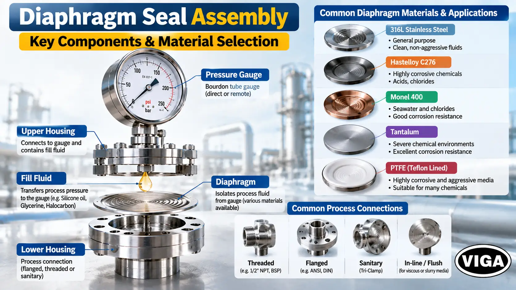
This table orients; it does not select. Corrosion rates swing with concentration, temperature and trace contaminants, so final compatibility must be confirmed against the manufacturer’s current corrosion data for the actual medium. WIKA also notes that PTFE coatings are generally offered on flanged rather than tapered-thread connections, since thread make-up can strip the coating.
Choosing the Seal Design
Diaphragm Seal Design & Mounting Selection
Process connection types, primary application suitability, and operational limitations
| Design | Best for | Limitation |
|---|---|---|
|
Threaded
|
General chemical service |
Small cavity can collect solids
|
|
Flanged
|
Larger diaphragms, linings, vessel nozzles |
Bulkier, costlier
|
|
Flush diaphragm
|
Viscous, sticky, crystallising media |
Needs a matching process nozzle
|
|
In-line (flow-through)
|
Slurries, CIP lines without dead space |
Must match pipe size
|
|
Sanitary clamp or dairy fitting
|
Food, dairy, pharma |
Pressure rating limited by clamp
|
|
Remote with capillary
|
Heat, vibration, awkward locations |
Head effect, slower response
|
|
Isolation ring (alternative)
|
Thick sludge, fibrous waste |
Narrower material choice, lower pressures
|
Fill Fluid Selection
WIKA describes fill fluid characteristics as a major factor behind seal performance, including response time, and offers dozens of fluids for specialised duties. Choose it alongside the diaphragm size, range, capillary length and mounting position.
Diaphragm Seal Fill Fluid Guide
System transmission fill fluids, application duties, and operating process constraints
| Fill fluid | Typical duty | Constraint |
|---|---|---|
|
Silicone oil
|
General process; commonly quoted around −40 to +200 °C |
Not for oxygen or oxidisers; banned on silicone-free sites
|
|
High-temperature silicone
|
Hot processes with capillary or cooler |
Vacuum capability falls as temperature rises
|
|
Glycerine
|
Non-vacuum service at moderate temperature |
WIKA advises against it on vacuum or compound ranges and with capillaries
|
|
Food-grade oil (e.g. FDA-compliant mineral oil or Neobee-type fluids)
|
Food, dairy, pharma |
Narrower temperature window
|
|
Halocarbon
|
Oxygen, chlorine, strong oxidisers |
Density close to double that of silicone, so larger head effect
|
Silicone-free requirements matter more than most specifiers expect. Paint and coating plants commonly prohibit silicone because trace contamination causes surface defects in the finish.
Vacuum is the other common failure point. At low absolute pressure, especially when hot, a fill fluid can begin to vaporise and the reading becomes unstable. WIKA offers specifically conditioned systems for these duties, which tells you how demanding vacuum service is.
The Error Budget: What a Seal Adds
A diaphragm seal does not change the gauge’s accuracy class. It adds separate error sources on top of it, and each one can be estimated before ordering.
- Gauge accuracy class. The starting point. EN 837-1 classes such as 1.0 or 1.6, or ASME B40.100 grades such as 1A, set the gauge’s own limit.
- Gauge temperature effect. Present with or without a seal. For WIKA’s standard Bourdon gauges it is up to ±0.4 % of span per 10 K from +20 °C.
- Fill fluid thermal expansion. The seal-specific term. Ashcroft points out that the absolute fill volume change does not depend on the pressure range, so the error as a percentage of span is larger on low ranges and smaller on high ones. Supplying process and ambient temperature ranges allows the manufacturer to calculate it for the exact assembly.
- Diaphragm stiffness. Small diaphragms on low ranges resist deflection enough to affect the reading.
- Head effect. When a capillary places the gauge above or below the seal, the column of fill fluid between them adds a constant hydrostatic offset:
Hydrostatic Head Effect Calculation
Capillary head correction formula and parameter specification for diaphragm seals
| Symbol | Meaning | Typical value |
|---|---|---|
|
ρ
|
Fill fluid density |
Silicone oil ≈ 970 kg/m³; halocarbon ≈ 1,850 kg/m³ or higher, depending on grade
|
|
g
|
Gravitational acceleration | 9.81 m/s² |
|
Δh
|
Vertical distance between gauge socket and seal diaphragm | metres |
|
10⁵
|
Conversion from Pa to bar | — |
The sign matters. A gauge mounted above the seal reads low, because the fill column hangs below it. A gauge mounted below the seal reads high, because the column adds its weight.
The gauge reads about 0.19 bar low across its entire scale. On a 0–10 bar gauge, that is close to 2 % of span, more than the entire accuracy class of a class 1.0 instrument. Swap to a halocarbon fill and the same installation produces roughly 0.36 bar.
The offset is fixed, so it can be removed. Either the manufacturer compensates for it at the factory, which requires the final height difference to be stated on the order, or it is corrected at commissioning using the gauge’s zero adjustment, where one is fitted. Once corrected, the gauge must stay at the height it was corrected for; relocating it later reintroduces the error.
Some manufacturers state accuracy for the complete factory assembly. WIKA’s DSS26M, a 100 mm Bourdon gauge with a mounted flange seal, is specified as class 1.0 as a system. Where a system figure is published, use it; where it is not, ask for the combined error in writing. Calibrate the seal and gauge together, never the gauge alone. The procedure is covered in calibrating a pressure gauge step by step.
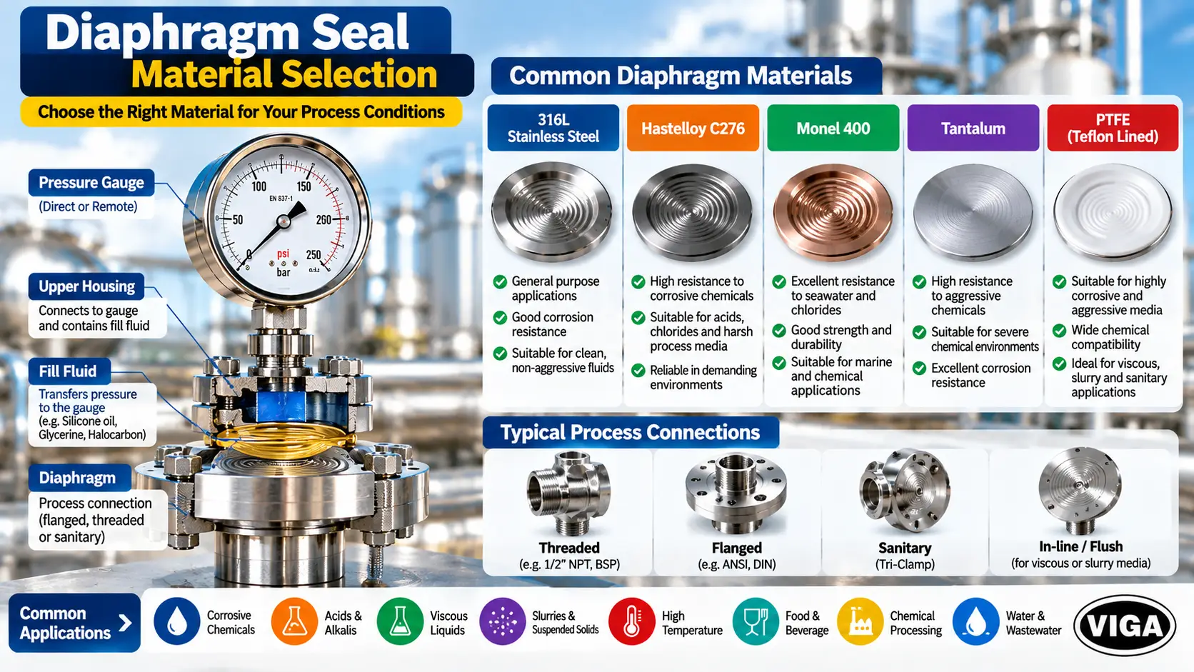
Diaphragm Seal vs Diaphragm Pressure Gauge
Same word, different instruments.
A diaphragm seal is an isolator. It transfers pressure through a filled system to a separate instrument, usually a Bourdon gauge, mounted directly or on a capillary.
A diaphragm pressure gauge, standardised under EN 837-3, uses a corrugated diaphragm as the measuring element itself. It is clamped between two flanges, often with an open process flange that can be cleaned, and its wetted parts can be coated or lined. It is generally suited to lower pressure ranges and to media that would plug a Bourdon tube.
Where both could work, pressure range, required accuracy, mounting and the specific design decide. For more on the diaphragm-element instrument, see What Is a Diaphragm Pressure Gauge and Where Is It Used?
Cost and Lifecycle
A seal assembly costs several times as much as a comparable direct gauge, and tantalum or lined diaphragms push that further. On clean service, the extra money buys nothing.
On difficult service, count what the direct gauge actually costs: how often it is replaced, the technician time each time, the hours of unreliable indication between failures, and the exposure risk if it leaks corrosive or toxic fluid. On a line that eats a gauge every few months, the seal usually pays for itself. On a line that loses one every few years, it often does not.
Maintenance changes too. A direct gauge is swapped in minutes behind an isolation valve. A sealed assembly is serviced as a unit, and refilling needs vacuum equipment. Seals with a removable lower housing or flushing ring allow cleaning without breaking the fill. Ashcroft advises against reusing a seal without inspection, since diaphragm damage is not always visible from outside.
Field Application Scenarios: Where Direct Bourdon Fails vs Where Seals Succeed
1. Caustic soda (NaOH) transfer line
What goes wrong: A 50 % caustic line runs warm, but during a shutdown the unheated gauge socket drops below about +12 °C. The caustic solidifies inside the Bourdon tube while the line still holds pressure. If that happens at 4 bar, the pointer can stay at 4 bar after the line is depressurised, and anyone reading it assumes the section is still live, or worse, assumes a later reading of 4 bar is real.
Root cause: Crystallisation in a dead-ended bore.
Fix: Flush-diaphragm seal with the seal face and nozzle heat-traced or steam-traced along with the line. 316L is commonly used for caustic at moderate temperature, but concentration and temperature must be checked against corrosion data, particularly for hot caustic.
Verify: Concentration, lowest ambient temperature, tracing arrangement.
2. ETP lime slurry and mixed waste stream
What goes wrong: Lime slurry and fibrous solids pack the 1/4″ or 1/2″ gauge socket within weeks. Standard threaded seals help briefly, then their lower cavity fills too.
Root cause: Settling solids in any stagnant cavity.
Fix: A full-bore in-line seal or an isolation ring with an elastomer sleeve, so solids pass straight through with no cavity. Isolation rings suit the lower pressures typical of effluent treatment.
Verify: Pipe size and flange standard, abrasiveness of solids, sleeve elastomer compatibility.
3. Hydraulic power unit
What goes wrong: On a piston-pump HPU, the pointer flutters so hard it cannot be read, and the movement teeth wear out within months.
Root cause: Pressure pulsation, not the fluid. Hydraulic oil is clean and compatible with a standard gauge.
Fix: A liquid-filled stainless gauge with a restrictor or snubber. A chemical seal here would add several times the cost and still leave pulsation to be dealt with.
Verify: Peak pressure including spikes; select the range so normal operation sits within the steady-pressure limit on the gauge datasheet.
4. Dairy CIP loop
What goes wrong: A direct Bourdon gauge on the product line has a coil that CIP chemicals and hot rinses never flush. Product residue sits in it between cleans.
Root cause: Dead leg in a hygienic process.
Fix: A flush sanitary seal on a tri-clamp fitting, polished wetted surface, filled with an FDA-compliant food-grade fluid. Use glycerine only on non-vacuum duty; switch to food-grade mineral oil if the loop pulls vacuum during cooling.
Verify: Clamp size and standard, CIP/SIP temperatures, required 3-A or EHEDG documentation.
5. Corrosive acid dosing
What goes wrong: A stainless gauge on a concentrated hydrochloric acid dosing line drifts, then weeps from the socket.
Root cause: 316L is not compatible; the thin tube corrodes through.
Fix: Flanged seal with a tantalum or suitably lined diaphragm, selected from the manufacturer’s corrosion data. Include the lower housing and gasket in the material check.
Verify: Exact concentration, maximum temperature, gasket material.
6. Hot reactor with remote reading
What goes wrong: A gauge mounted on a vessel nozzle well above +200 °C fogs, discolours and loses accuracy.
Root cause: Medium temperature beyond the gauge’s datasheet limit.
Fix: Seal with a capillary and high-temperature fill, gauge mounted at an accessible, cooler point.
Verify: Capillary length, height difference (for head correction), ambient range, fill fluid limits, and vacuum if the reactor ever runs below atmospheric.
Plant Floor Procurement & RFQ Engineering Matrix
Most seal enquiries stall on missing data. The matrix below is what a selection engineer needs before a gauge or seal can be configured, along with where each value normally comes from on site.
Specification Data Checklist
Critical process, operating conditions, and site parameters required before specifying instrumentation
| Parameter | Required value / how to establish it |
|---|---|
|
Process medium
|
Chemical name, not trade name; attach the SDS where available |
|
Concentration
|
Worst-case (highest) concentration, including after upsets or dosing peaks |
|
Contaminants
|
Chlorides, fluorides, solvents, abrasives; any trace species that changes corrosion behaviour |
|
Solids content
|
Present or absent; particle type (crystalline, fibrous, abrasive) and approximate size |
|
Behaviour when cold
|
Does the fluid thicken, gel or crystallise at the lowest ambient temperature? Check the removed gauge socket |
|
Operating temperature
|
Normal process temperature at the measuring point |
|
Maximum temperature
|
Highest value including start-up, steam-out and CIP/SIP cycles |
|
Ambient range
|
Lowest winter night and highest summer surface temperature at the gauge location |
|
Pressure range
|
Normal operating pressure; normal reading should sit within the gauge's steady-pressure limit |
|
Peak and minimum pressure
|
Pump spikes, water hammer, and lowest absolute pressure if the line ever pulls vacuum |
|
Pulsation and vibration
|
Pump type (piston, centrifugal); visible pointer flutter; pipe vibration at the mounting point |
|
Process connection
|
Type (thread, flange, clamp, in-line), size, standard and rating |
|
Required accuracy
|
Accuracy class or grade needed for the application, stated for the complete assembly |
|
Mounting
|
Direct or remote; capillary length; vertical height between seal and gauge in metres |
|
Hygiene requirements
|
CIP/SIP conditions, surface finish, 3-A or EHEDG documentation if required |
|
Site restrictions
|
Silicone-free area, oxygen or oxidiser service, hazardous-area classification |
|
Failure history
|
What the previous gauge showed when removed (see the diagnostic table above) |
A handover note that fills every row of this matrix usually turns a week of back-and-forth into a single quotation. The questions below are the ones that still come up after the matrix is filled in.
Frequently Asked Questions
Q2. When is a diaphragm seal necessary?
A diaphragm seal is necessary when the process fluid would corrode, plug, crystallise in or harden inside the Bourdon tube, when a hygienic process cannot accept a dead-ended cavity, or when medium temperature exceeds the gauge limit, typically +60 °C for copper-alloy and +200 °C for unfilled stainless gauges.
It is also justified with toxic or hazardous media, where a failure of the thin tube wall carries serious consequences. Corrosion alone does not force a seal if a compatible tube material exists.
Q2. When is a direct Bourdon gauge sufficient?
A direct Bourdon gauge is sufficient for clean, solids-free fluids that remain freely flowing at the lowest line temperature, are compatible with the wetted material, and stay within the datasheet medium limit. Compressed air, clean water, hydraulic oil and siphon-protected steam are typical examples.
On these services a seal only adds cost, error and maintenance complexity.
Q3. Does a diaphragm seal reduce pressure gauge accuracy?
Yes, a diaphragm seal adds error on top of the gauge’s accuracy class. The main sources are fill fluid thermal expansion, diaphragm stiffness and head effect, which is about 0.095 bar per metre of height difference with silicone fill. Effects are largest on low pressure ranges with small diaphragms.
Ask the supplier for the combined error of the complete assembly, and calibrate seal and gauge together.
Q4. Which diaphragm material should be selected?
316L stainless steel covers many general services. Hastelloy C276 suits many chloride and mixed-acid duties, Monel 400 suits hydrofluoric acid and brine, tantalum suits strong acids such as hydrochloric, and PTFE coatings offer broad resistance. Final choice must be verified against the manufacturer’s corrosion data.
Concentration, temperature and trace contaminants all change the answer, and the lower housing and gasket need the same check.
Q5. What type of seal is suitable for slurry?
For slurry, use a flush-diaphragm seal or a full-bore in-line seal, which leave little or no cavity for solids to settle in. For thick sludge and fibrous waste at lower pressures, an isolation ring with a flexible sleeve is often the better choice.
Threaded seals with a cavity above the connection tend to plug on these services.
Q6. What fill fluid should be used in a diaphragm seal?
Silicone oil suits most general process service. Food-grade mineral oil or similar FDA-compliant fluids suit food and pharma. Halocarbon is used for oxygen, chlorine and strong oxidisers. Glycerine is limited to non-vacuum service without capillaries. Temperature, vacuum and site restrictions decide the final choice.
Silicone-free sites, such as paint shops, rule out silicone fills entirely.
Q7. Is a diaphragm seal the same as a diaphragm pressure gauge?
No. A diaphragm seal is an isolator that transmits pressure through a fill fluid to a separate gauge, usually a Bourdon type. A diaphragm pressure gauge (EN 837-3) uses the diaphragm itself as the measuring element and is generally applied to lower pressure ranges.
Both handle difficult media, but they are different instrument architectures with different range and mounting envelopes.
Q8. Can an existing Bourdon gauge be fitted to a diaphragm seal?
Not reliably in the field. A seal and gauge must be assembled, evacuated and filled together under controlled conditions, and the gauge must be suitable for seal mounting. Order a factory-filled assembly matched to the process.
Field-assembled systems typically trap air, which produces sluggish, temperature-sensitive readings.
Q9. When is a diaphragm seal unnecessary?
A diaphragm seal is unnecessary on clean, compatible service, and it is the wrong fix for pulsation, vibration, steam or overpressure. Those problems are solved with a snubber or restrictor, a liquid-filled gauge, a siphon or a gauge saver respectively.
Adding a seal in these cases increases cost and error without addressing the cause.
Final Selection Guidance
Start from the fluid at its worst: coldest, most concentrated, dirtiest. If a direct gauge survives that condition within its datasheet limits, use one. If it does not, specify the seal style, diaphragm material and fill fluid together, because the assembly is only as good as its weakest choice. And before paying for a seal, confirm the failure really comes from the fluid and not from pulsation, vibration, steam or overpressure.
Selection Support from VIGA
VIGA (Vinod Gautam Sales), based at Chawri Bazar in Delhi, supplies pressure instrumentation to industrial users as an Authorized Distributor of WIKA and Mass. The Mass range on the VIGA website includes diaphragm seals alongside pressure gauges, and the WIKA range includes Bourdon tube and liquid-filled gauges such as the WIKA 213.53 liquid-filled gauge.
For a gauge or gauge-and-seal recommendation, share the completed RFQ matrix above, or the process datasheet for the measuring point, through the VIGA contact page. With those parameters in hand, the configuration can be checked against WIKA and Mass selection data, and gaps such as a missing concentration, an unstated height difference or an unconfirmed vacuum condition can be resolved before a quotation is prepared.