

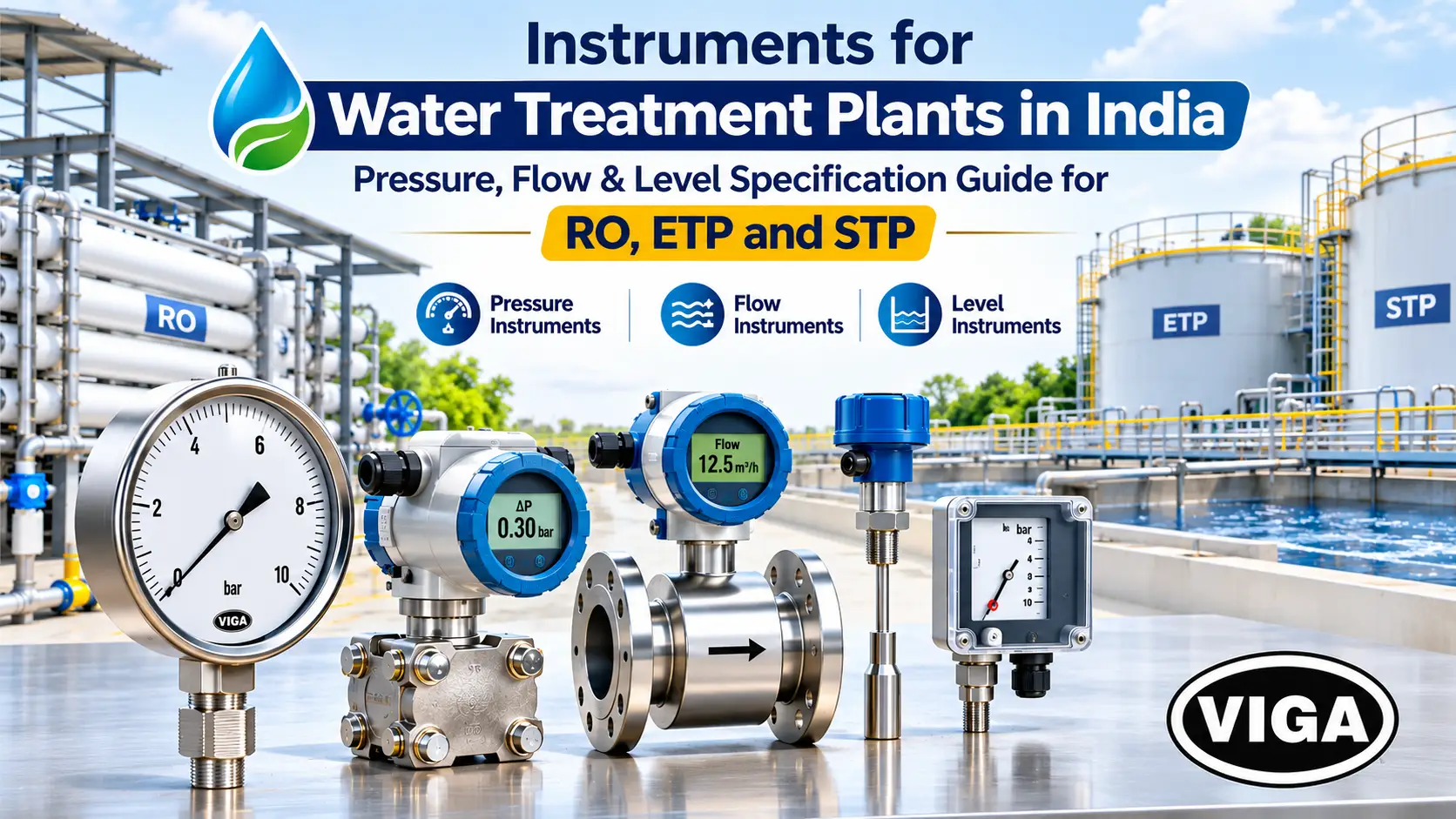
Instruments for Water Treatment Plants in India: Pressure, Flow & Level Specifications for RO, ETP and STP
The short answer: select water treatment plant instruments based on operating pressure, flow requirements, tank levels, chemical compatibility and site conditions. Use SS 316 pressure gauges for suitable water applications, dedicated differential pressure instruments for filter monitoring, diaphragm seals for corrosive chemical lines, and properly ranged pressure gauges and transmitters for RO systems. Choose flow meters according to water conductivity and level sensors according to tank conditions. Correct instrument selection, installation and calibration help improve plant reliability, prevent equipment failures and maintain efficient RO, ETP and STP operations.
Most pressure gauges in Indian water plants do not fail on a test bench. They fail in the field: a Bourdon tube pitted from inside by hypochlorite, a dry gauge with needle flutter on a dosing pump discharge, a pressure switch tripping on its own because monsoon condensation filled the terminal box. Choosing instruments for a water treatment plant in India means designing out these failures before the purchase order. Whether the job is ETP STP instrumentation for a consent renewal or an RO plant pressure gauge on a membrane train, sound water treatment instrumentation comes down to three choices: range, wetted material and environmental protection.
A water treatment plant lives or dies by its instrumentation. Get the pressure and differential monitoring right and the plant runs itself. Get it wrong and the operators spend every shift chasing symptoms that a correctly specified instrument would have flagged weeks earlier.
What follows is organised the way a commissioning engineer walks a plant: from the raw water sump to the treated water outlet, with the material matrix and the full instrument schedule at the end for anyone building a datasheet.
Why Standard Gauges Fail in Indian Water Treatment Plants
Standard industrial gauges fail in Indian water plants because four conditions hit them together: aggressive chemistry (chlorides, hypochlorite, acids), small differential signals riding on high static pressure, round-the-clock pump pulsation, and outdoor exposure to 45°C summers, monsoon humidity and dust. A gauge must be specified for all four.
Water looks like the gentlest process medium on a site. On paper, a 0–10 bar brass gauge from the nearest market should handle it. In practice, that gauge lasts until its first summer on an RO reject line.
- The chemistry is hostile to ordinary metals. Treated water carries residual chlorine. Dosing skids carry sodium hypochlorite, hydrochloric or sulphuric acid, alum, ferric chloride, caustic and antiscalant. RO reject concentrates chlorides several times over. Brass dezincifies. SS 304 pits. Even SS 316 pits under stagnant, warm, high-chloride conditions, which is exactly what exists inside a gauge socket that never gets flushed.
- The useful signal is a small difference. An RO first stage might run at 14 bar, but the number that reveals fouling is a pressure drop of 1–2 bar across the vessels. A pressure sand filter runs at 3–4 bar, but the backwash signal is a fraction of a bar between inlet and outlet. Measuring a small delta-P on top of a large static pressure is a precision job, and most plants treat it as plumbing.
- The plant never stops. Raw water pumps, high-pressure pumps and diaphragm dosing pumps run day and night. Pulsation fatigues the Bourdon tube, wears the movement and turns a dry gauge’s pointer into a blur. Water hammer thuds from pump trips and fast-closing valves push transient pressure well past the dial.
- The installation is outdoors, in North India. Across Gurgaon, Faridabad, Okhla and Noida, a large share of ETPs and RO plants sit in open sheds. Summer ambients cross 45°C, enough to discolour glycerine fill and shift zero on cheaper gauges. Monsoon months bring condensation inside switch housings and junction boxes. Dust packs every unsealed vent. Add borewell water that often sits above the BIS IS 10500 acceptable limit for total dissolved solids, and the instrument is fighting scale, corrosion and heat at the same time.
The takeaway is simple. Every instrument in a water plant must be specified on three axes at once: what it measures, what touches it, and where it sits. Get one right and ignore the other two, and the instrument becomes a maintenance ticket within a year.
The Math of Differential Pressure: Why Two Independent Gauges Always Fail
Two separate gauges cannot measure filter differential pressure reliably because their individual errors add up. Two 0–10 bar, Class 1.0 gauges each carry ±0.1 bar error, giving up to ±0.2 bar combined error on a clean filter delta-P of only 0.3 bar. A dedicated DP instrument removes that problem.
The most common shortcut in water plants is an inlet gauge, an outlet gauge, and an operator doing subtraction on the log sheet. The arithmetic shows why this does not work.
| Condition | True ΔP | What two gauges can show (worst case) |
|---|---|---|
| Clean bed after backwash | 0.3 bar | 0.1 to 0.5 bar |
| Bed half loaded | 0.6 bar | 0.4 to 0.8 bar |
| Backwash set point | 0.8 bar | 0.6 to 1.0 bar |
A half-loaded bed can read as ready for backwash. A bed that is overdue can read as fine. The error band covers most of the filter’s working range, before counting parallax, different mounting heights, and two gauges ageing at different rates.
Compare that with a dedicated differential pressure gauge on a 0–1.6 bar span at Class 1.6:
Roughly eight times tighter than the worst case from two line gauges, on the same filter, from one instrument.
Choose the DP instrument by what the signal has to do:
- DP gauge for local reading on rounds, typical on cartridge filter housings and small plants.
- DP switch where the only job is an alarm or a backwash start. This is the standard backwash pressure switch.
- DP transmitter (4–20 mA to PLC or SCADA) where trending matters. A slow, steady rise is normal loading. A sudden jump points to an upstream disturbance. A delta-P that refuses to come back down after backwash points to mudballing or channelling in the media.
Two specification details catch people out. Every DP instrument has a maximum static (line) pressure rating, and it must exceed the process pressure; a DP switch built for 4 bar sand filters cannot go onto a 15 bar RO stage. And every DP transmitter needs a three-valve or five-valve manifold so it can be isolated, equalised and zero-checked without shutting the line.
Point-by-Point Instrument Specification Across the Process Train
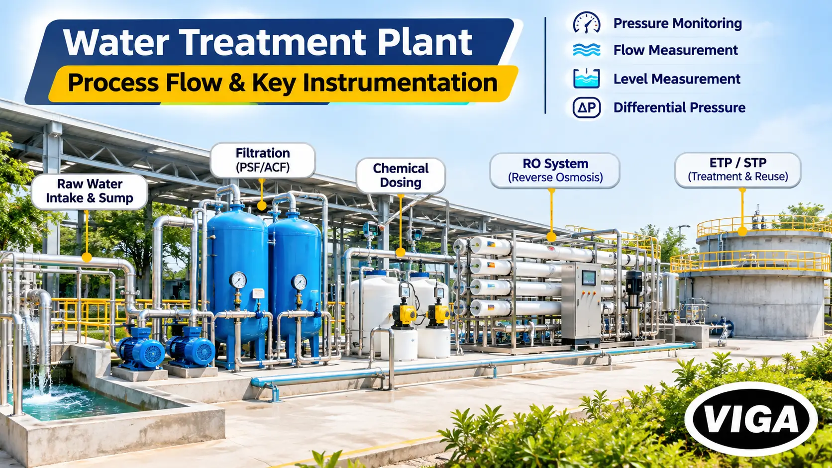
A water treatment plant needs pressure monitoring at every pump, differential pressure across every filter and membrane stage, level measurement on every tank and sump, and flow measurement at intake, RO streams and discharge. Range, wetted material and protection change with each process area.
Raw Water Intake, Sumps & Pumping
At the intake, each raw water pump needs a compound gauge on suction, a liquid-filled gauge on discharge, and a low-pressure or level-based dry-run interlock. Sumps need a level transmitter: hydrostatic for clean water, radar for effluent sumps carrying solids, grease or foam.
Pump pressure monitoring starts at the suction flange. A compound gauge, reading vacuum and positive pressure on one dial (for example −1 to +3 bar), is the right choice because suction conditions swing between flooded and lift as the sump level moves. A suction reading that drifts deeper into vacuum is the earliest sign of foot valve choking, a blocked strainer or a falling sump. Operators who learn to read that dial catch problems a shift before the pump starts cavitating.
The discharge gauge confirms delivered head. Liquid-filled, SS 316 wetted, and fitted with a snubber where the pump is reciprocating or the line is prone to water hammer.
Dry-run protection should never rely on one device. A low-pressure switch on the pump discharge, a low-level signal from the sump, and an independent float switch together give a trip that survives a single failure.
For the level transmitter on a water tank or sump, the medium decides the technology:
| Sump / tank | Recommended level technology | Reason |
|---|---|---|
|
Clean raw water, treated water
|
Hydrostatic submersible transmitter | Simple, low cost, reliable in clean water |
|
ETP collection / equalisation sump
|
Non-contact radar | Solids, grease and rags foul submersible sensors |
|
Aeration tank with foam
|
Radar | Foam absorbs ultrasonic pulses |
|
Chemical day tanks
|
Radar or suitably rated hydrostatic | Chemical compatibility of wetted parts |
An electromagnetic flow meter on the raw water main sets the baseline every downstream flow is checked against.
Media Filtration & Auto-Backwash Sequence
Pressure sand and activated carbon filters need inlet and outlet gauges plus a DP switch or DP transmitter across each vessel. The DP signal triggers backwash through pneumatically actuated butterfly valves, with solenoid valves switching actuator air. A pressure switch on the backwash pump confirms flow.
A filter is a pressure-drop machine. Clean media passes water easily; as the bed loads with suspended solids, delta-P climbs until backwash is due. Running backwash on a fixed timer means either washing beds that still had capacity (wasting treated water) or washing beds that were already breaking through.
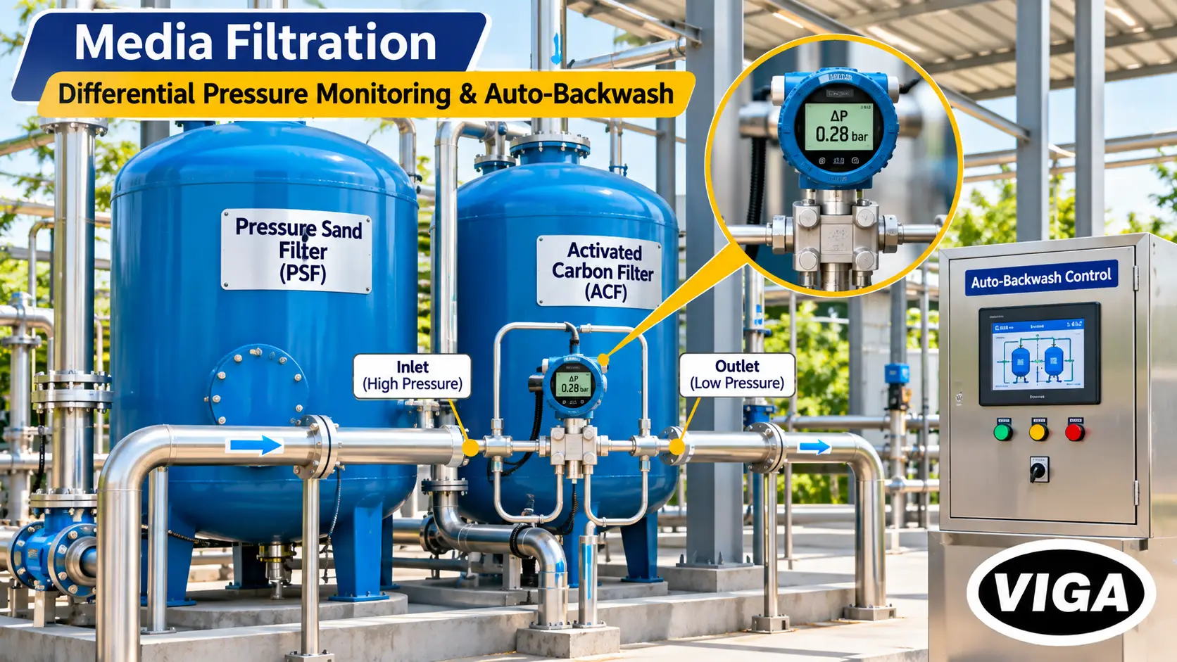
The automated sequence on most industrial plants looks like this:
- DP switch or DP transmitter crosses the set point taken from the filter manufacturer’s design data.
- PLC closes the service inlet and outlet valves, typically pneumatically actuated butterfly valves on larger lines.
- Solenoid valves route instrument air to the backwash inlet and drain valve actuators.
- Backwash pump starts; a pressure switch on its discharge confirms the filter is receiving flow.
- Rinse step, then return to service. The PLC logs the post-backwash delta-P as the new clean baseline.
A three-valve manifold on the DP transmitter, and a properly prepared air supply (filter-regulator ahead of the solenoid valves) are what keep this sequence reliable. Wet, dirty instrument air is a frequent reason actuators stick half-open.
Cartridge filters ahead of an RO system belong in this section as well. They are the last line of membrane protection, and a DP gauge across each housing is the only honest way to decide cartridge change-out.
Reverse Osmosis (RO) Membrane Stages
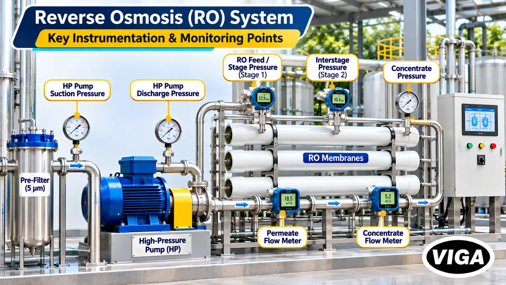
In an RO plant, every membrane stage needs differential pressure monitoring. The minimum list: low-pressure trip on HP pump suction, high-pressure trip on discharge, pressure at feed, interstage and concentrate, permeate pressure protection, and flow on permeate and concentrate to calculate recovery.
In an RO plant, every membrane stage needs differential pressure monitoring. Here is the full instrument list for a typical two-stage brackish water system.
| Point | Instrument | Why it is there |
|---|---|---|
|
HP pump suction
|
Pressure gauge + low-pressure switch | Trips the pump when cartridges clog or feed fails; prevents dry running |
|
HP pump discharge
|
Pressure gauge + high-pressure switch | Protects vessels and membranes against overpressure, e.g. a closed concentrate valve |
|
Stage 1 feed
|
Pressure transmitter + gauge | Start of stage 1 delta-P |
|
Interstage
|
Pressure transmitter + gauge | End of stage 1, start of stage 2 |
|
Concentrate (reject)
|
Pressure transmitter + gauge | End of stage 2 delta-P; recovery control |
|
Permeate header
|
Pressure gauge (transmitter preferred) | Detects dangerous permeate backpressure |
|
Permeate flow
|
Flow meter | Recovery calculation |
|
Concentrate flow
|
Flow meter | Recovery calculation |
Three engineering points separate a well-instrumented RO from an average one.
Stage delta-P is the fouling and scaling alarm. Membrane manufacturers publish cleaning criteria that typically call for a clean-in-place when normalised differential pressure rises around 15% above the startup baseline. Without transmitters at feed, interstage and concentrate, that rise is invisible until permeate flow has already collapsed. Record the baseline at commissioning; every later reading is judged against it.
Permeate backpressure can destroy elements. Membrane manufacturers specify that permeate pressure must never exceed feed or concentrate pressure by more than a small margin, commonly around 0.3 bar. A permeate valve left closed during startup, or a permeate line routed to an elevated tank without a check, can delaminate elements. A permeate pressure switch interlocked with the HP pump is cheap insurance.
Range the gauges properly. EN 837-2 selection guidance keeps steady operating pressure below roughly 75% of full scale, and pulsating pressure below about two-thirds. In practice, an RO plant pressure gauge works best when normal pressure sits in the middle third of the dial: a 12 bar system takes a 0–25 bar gauge, not 0–16 bar (no headroom for spikes) and not 0–100 bar (unreadable resolution). On the high-pressure side, insist on SS 316 wetted parts, a stainless steel case and glycerine fill. Over time, a slow, steady pressure creep at constant flow on older trains can also indicate membrane compaction, another reason to trend rather than spot-read.
Chemical Dosing Skids & Corrosive Lines
Gauges on dosing lines must never let the chemical reach the Bourdon tube. Use a diaphragm seal with a diaphragm material matched to the chemical (tantalum, Hastelloy C-276 or PTFE-lined), a PVDF or PP seal body, and a pulsation dampener or snubber against diaphragm-pump pulses.
Dosing skids are where most instrument budgets are lost. Diaphragm metering pumps deliver chemical in sharp pulses, and the chemicals themselves (hypochlorite, acid, ferric chloride, alum) are among the most corrosive substances on site.
A standard SS 316 gauge screwed directly into a hypochlorite line will pit, leak and seize. The fix is a diaphragm seal isolator: a flexible diaphragm separates the process chemical from a fill fluid that transmits pressure to the gauge. The chemical never enters the narrow tube, so crystallising chemicals such as alum and ferric chloride cannot block it either.
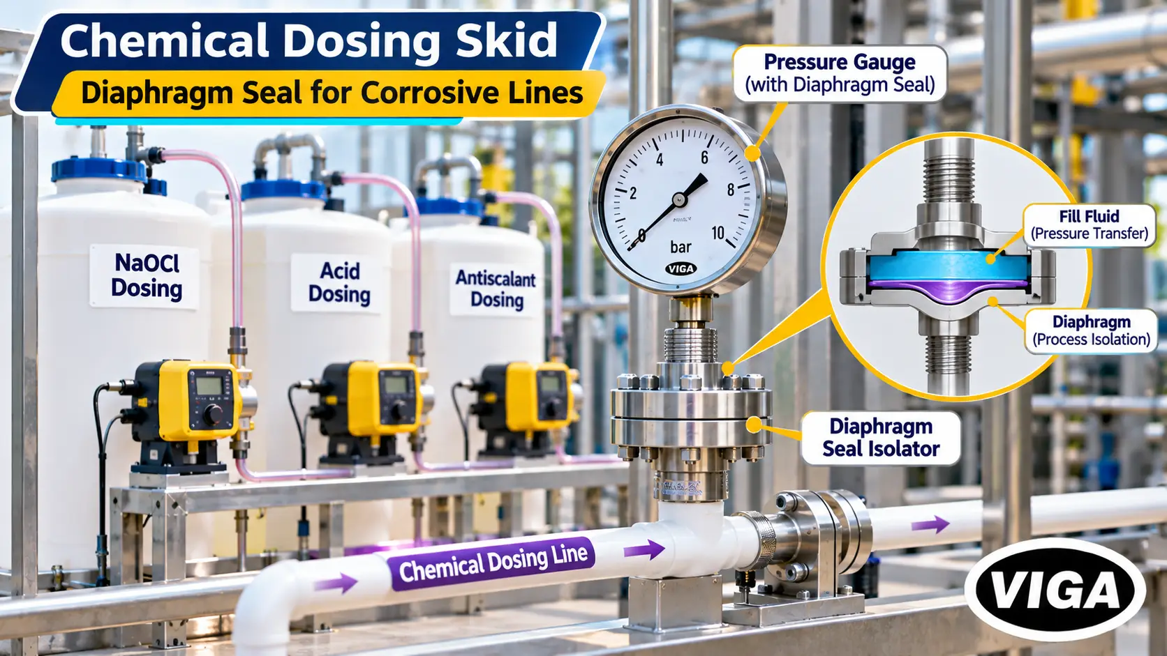
A pulsation dampener on the pump discharge, plus a snubber or restrictor at the gauge, stops needle flutter and protects the movement. Without them, a dosing-line gauge is unreadable and short-lived, and the operator loses the only quick indication of a failed pump diaphragm or a blocked injection quill.
Leaks at pump glands and fittings on these skids also corrode nearby instruments from the outside. Gland packing leaks drip acid onto painted steel cases; stainless steel cases and sensible mounting positions above the skid avoid that.
Treated Water Distribution & SPCB Compliance
Distribution needs a pressure transmitter on the header for VFD constant-pressure control, snubbered gauges against water hammer, level transmitters on storage tanks, and reliable outlet flow measurement. Electromagnetic flow meters suit most treated water but fail on very low-conductivity permeate, so check conductivity first.
On the outlet side, instrumentation shifts from process control to delivery and accountability.
A header pressure transmitter feeding the VFD keeps supply pressure constant and cuts pump energy. Gauges on distribution lines need snubbers or gauge savers, because water hammer from pump trips and quick-closing valves is routine.
Flow measurement at the treated water outlet and at the ETP or STP discharge is where compliance enters. State Pollution Control Board consent conditions govern discharge, and under CPCB directions, highly polluting industry categories and common effluent treatment plants are required to run online continuous effluent monitoring connected to the regulator. Requirements vary by industry category and state, so confirm the current conditions with the relevant SPCB before finalising the outlet instrument package. SPCB consent audits invariably start with whether the discharge flow figure can be trusted.
Mag meter conductivity limits. Electromagnetic flow meters need a minimum fluid conductivity to generate a signal, typically around 5 µS/cm for many designs (always check the specific datasheet). Raw water, ETP effluent and single-pass RO permeate usually clear this. Permeate from a second-pass RO or a polishing stage can fall below it, producing unstable or zero readings. On those lines, ultrasonic, vortex or variable-area meters are the safer choice.
Chemical & Wetted Material Compatibility Matrix
SS 316 suits raw, treated and normally chlorinated water and caustic. Hypochlorite, hydrochloric acid and ferric chloride need diaphragm seals with tantalum, Hastelloy C-276 or PTFE-lined diaphragms. Brass suits only clean utility water. Tantalum must not be used with strong caustic. Always confirm against concentration and temperature.
| Medium | Typical concentration in plant | SS 304 | SS 316 / 316L | Hastelloy C-276 | Tantalum | PTFE (lined diaphragm) | PVDF / PP (seal body) | Recommended approach |
|---|---|---|---|---|---|---|---|---|
|
Raw water, treated water
|
— | Fair | Good | Good | Good | Good | Good | SS 316 direct mount |
|
Chlorinated water (residual)
|
Low ppm | Fair | Good | Good | Good | Good | Good | SS 316 direct mount |
|
Sodium hypochlorite
|
Dosing strength | Poor | Poor | Limited, confirm | Good | Good | Good | Diaphragm seal, tantalum or PTFE-lined, PVDF body |
|
Hydrochloric acid
|
Dosing strength | Poor | Poor | Limited at ambient, confirm | Good | Good | Good | Diaphragm seal, tantalum or PTFE-lined |
|
Sulphuric acid
|
Dilute to concentrated | Poor | Concentration-dependent | Good | Good | Good | Concentration-dependent | Diaphragm seal; confirm against concentration |
|
Ferric chloride
|
Coagulant strength | Poor | Poor | Limited, confirm | Good | Good | Good | Diaphragm seal, tantalum or PTFE-lined |
|
Alum
|
Coagulant strength | Poor | Fair | Good | Good | Good | Good | Diaphragm seal (also prevents crystallisation) |
|
Caustic soda (NaOH)
|
Dosing / CIP | Fair | Good | Good | Not suitable | Good | PP good; PVDF confirm | SS 316 or seal with Hastelloy / PTFE |
|
Antiscalant, SMBS
|
Dosing strength | Fair | Good | Good | Good | Good | Good | SS 316, seal if crystallising |
|
RO reject, brine, seawater
|
High chloride | Poor | Pitting risk | Good | Good | Good | Good | SS 316 minimum; higher alloy for high-chloride service |
|
Sludge, raw sewage
|
Solids-laden | Fair | Good | Good | Good | Good | Good | Flush diaphragm seal to prevent socket blockage |
Ratings are general engineering guidance for ambient temperatures. Final selection must be confirmed against the OEM corrosion data for the actual concentration and temperature.
A chlorine resistant gauge, then, is not a single product. For normal chlorinated water, a good SS 316 gauge is adequate. For the hypochlorite dosing line, the gauge must be isolated with a diaphragm seal.
Outside the wetted parts, three more choices decide field life:
- Case: stainless steel case with weatherproof ingress protection for open sheds and washdown areas. Painted steel cases rust within a monsoon or two.
- Fill: glycerine for vibration and pulsation damping. Where heat or UV discolours glycerine on exposed gauges, ask about silicone oil fill and shading. Confirm fill compatibility wherever an oxidising chemical could reach it.
- Electrical: correctly rated cable glands, sealed housings and drain points on switches and transmitters. Condensation in terminal boxes is behind a large share of monsoon false trips.
Master Water Plant Instrument Schedule
A complete water plant schedule covers intake pumps, sumps, dosing skids, media and cartridge filters, RO stages, ETP/STP aeration and sludge lines, distribution and discharge. Each line specifies parameter, instrument type, wetted material and range, sized so normal operation sits within the middle of the span.
| Area | Parameter | Instrument type | Recommended wetted material | Ideal range / span | Key OEM brands (via VIGA) |
|---|---|---|---|---|---|
|
Raw water pump suction
|
Pressure / vacuum | Compound gauge, liquid filled | SS 316 | e.g. −1 to +3 bar, per suction conditions | WIKA, Mass, VIGA (manufactured) |
|
Raw water pump discharge
|
Pressure | Liquid-filled gauge + snubber | SS 316 | 1.5–2× normal operating pressure | WIKA, Mass, VIGA (manufactured) |
|
Raw water pump
|
Dry-run protection | Pressure switch | SS 316 / brass for clean water | Set point below normal discharge | Indfos, Switzer |
|
Clean water sump / tank
|
Level | Hydrostatic level transmitter | SS 316 | Tank height + margin | Specify per project |
|
ETP sump / aeration tank
|
Level | Non-contact radar | Non-wetted | Tank height + margin | Specify per project |
|
Raw water main
|
Flow | Electromagnetic flow meter | Liner and electrodes to suit water | Sized to line velocity | Specify per project |
|
Dosing skid (hypo, acid, FeCl₃)
|
Pressure | Gauge + diaphragm seal | Tantalum / PTFE-lined diaphragm, PVDF body | 1.5–2× pump discharge | WIKA, Mass |
|
Dosing pump discharge
|
Pulsation | Pulsation dampener / snubber | Compatible with chemical | — | Mass |
|
Pressure sand / carbon filter
|
Inlet / outlet pressure | Liquid-filled gauge | SS 316 | 0–6 or 0–10 bar typical | WIKA, Mass, VIGA (manufactured) |
|
Pressure sand / carbon filter
|
Differential pressure | DP switch or DP transmitter + 3-valve manifold | SS 316 | Span covering backwash set point with headroom | Switzer, WIKA, Mass (manifolds) |
|
Backwash pump
|
Flow confirmation | Pressure switch | SS 316 | Set below backwash pressure | Indfos, Switzer |
|
Backwash valves
|
Actuation | Actuated butterfly valve + solenoid valve | Cast iron / SS body, seat to suit water | Line size | Uflow |
|
Actuator air supply
|
Air preparation | Filter-regulator | — | Actuator supply pressure | Shavo, Uflow |
|
Cartridge filter
|
Differential pressure | DP gauge | SS 316 | Span covering change-out point | WIKA, Mass |
|
RO HP pump suction
|
Pressure + trip | Gauge + low-pressure switch | SS 316 | Per feed pressure | WIKA, Mass, Indfos |
|
RO HP pump discharge
|
Pressure + trip | Gauge + high-pressure switch | SS 316 | Normal pressure in middle third (e.g. 0–25 bar at 12 bar) | WIKA, Mass, Indfos, Switzer |
|
RO feed / interstage / concentrate
|
Pressure, stage ΔP | Pressure transmitters + gauges | SS 316 (higher alloy for seawater) | Per design pressure | WIKA, Mass |
|
RO permeate
|
Backpressure | Gauge / pressure switch | SS 316 | Low range, per permeate pressure | WIKA, Mass, Indfos |
|
RO permeate / concentrate
|
Flow | Flow meter (check conductivity) | To suit service | Per design flow | Specify per project |
|
ETP / STP blower header
|
Air pressure | Low-range gauge | SS 316 | Low pressure scale to suit blower | WIKA, Mass |
|
ETP / STP sludge line
|
Pressure | Gauge + flush diaphragm seal | SS 316 | Per pump discharge | WIKA, Mass |
|
Distribution header
|
Pressure | Pressure transmitter + snubbered gauge | SS 316 | Per header design pressure | WIKA, Mass |
|
Treated water / discharge
|
Flow | Flow meter | To suit service | Per discharge flow | Specify per project |
Level and flow technologies marked “Specify per project” sit outside the current viga.in catalogue and should be specified against the plant design.
VIGA manufactures its own pressure and vacuum gauges in India for general utility points, and supplies WIKA, Mass, Switzer, Indfos, Uflow and Shavo as an authorized distributor. On water projects, the authorized channel is what makes documentation traceable: OEM test certificates, material certificates for wetted parts, and calibration records that consultants and municipal clients ask for at handover. Buyers should specify the certificates required in the purchase order rather than requesting them after delivery.
Costly Field Mistakes to Avoid
The costliest water plant instrumentation mistakes are oversized gauge ranges, brass gauges on brine or chlorinated lines, two-gauge filter delta-P, unprotected dosing gauges, mag meters on low-conductivity permeate, ultrasonic level over foam, missing isolation valves, and no commissioning baseline. Each is cheap to prevent at design.
These show up during commissioning and in the first year of operation, over and over.
Oversized ranges. A 0–40 bar gauge on a pump running at 4 bar puts the pointer in the first tenth of the dial. Nobody can read a 0.2 bar change there.
Brass on the wrong line. Brass is acceptable on clean utility water. On RO reject, brine or chlorinated service it dezincifies, and readings drift long before the gauge visibly fails.
Two-gauge delta-P. Covered in the math section. It produces backwash decisions that are close to random.
Bare gauges on dosing pumps. No diaphragm seal, no snubber. The gauge is dead in months and the operator has lost the only quick check on the dosing pump.
Mag meters on polished permeate. Below the meter’s minimum conductivity, the reading wanders or drops to zero, and someone eventually logs it as a meter fault.
Ultrasonic level over foam. ETP aeration and equalisation tanks foam. Ultrasonic echoes get lost; radar does not have this problem.
No isolation valve or manifold. An instrument that cannot be isolated never gets removed for calibration. In practice, it simply stops being trusted.
No baseline at commissioning. Without clean delta-P values for every filter and RO stage, later readings mean nothing. Write them on the commissioning report and on a tag at the instrument.
DP switch static rating ignored. A low-pressure DP switch reused on an RO stage can fail at the sensing element the first time the HP pump starts.
Calibration treated as optional. Gauges, switches and transmitters drift. A documented calibration schedule, with certificates on file, protects process performance and SPCB audit readiness alike.
Frequently Asked Questions (FAQ)
Q1. Which pressure gauge is best for an RO plant?
An RO plant needs liquid-filled pressure gauges with stainless steel cases and SS 316 wetted parts, sized so normal pressure sits in the middle third of the dial. A system at 12 bar suits a 0–25 bar gauge. Seawater or high-chloride service needs wetted material confirmed with the supplier.
Gauges are required at HP pump suction and discharge, at feed, interstage and concentrate, and on the permeate header, with trips on suction (low) and discharge (high).
Q2. What material is chlorine resistant for pressure gauges?
For normally chlorinated water, SS 316 wetted parts are adequate. For sodium hypochlorite and concentrated chlorine chemicals, use a diaphragm seal with a tantalum or PTFE-lined diaphragm (Hastelloy C-276 only after confirming concentration) and a PVDF or PP seal body, keeping chemical out of the gauge.
Q3. What differential pressure range should be used for filter monitoring?
Size the DP range to the filter’s pressure drop, not the line pressure. The backwash set point should sit comfortably within the span, with headroom above it for abnormal loading. Take clean and backwash values from the filter manufacturer, and make sure the instrument’s static pressure rating exceeds line pressure.
Q4. Why does an electromagnetic flow meter read zero on RO permeate?
Electromagnetic flow meters need a minimum fluid conductivity, often around 5 µS/cm depending on design. Permeate from a second-pass RO or polishing stage can fall below that limit, producing unstable or zero readings. Ultrasonic, vortex or variable-area meters are better suited to very low-conductivity water.
Instrumentation Support for Water Projects in Delhi NCR
Plant engineers, ETP and STP contractors and project consultants across Okhla, Faridabad, Gurgaon, Noida, Wazirpur, Mayapuri, Kirti Nagar and the Baddi industrial belt work with VIGA on instrument schedules for new water plants and retrofits. The water sector range covers VIGA-manufactured pressure and vacuum gauges, WIKA and Mass gauges, diaphragm seals, transmitters and manifolds, Switzer and Indfos pressure and differential pressure switches, Uflow solenoid valves and actuated butterfly valves for backwash automation, and Shavo air preparation for valve actuators, supplied through the authorized distribution channel.
For project consultation, bulk schedules or selection support:
Vinod Gautam Sales (VIGA) 20, Chawri Bazar, Delhi – 110006 Phone: +91-11-43025959 | +91-11-41582888 Email: [email protected] Website: viga.in