

How to Install a Pressure Transmitter: Step-by-Step Guide to 4–20mA Wiring, Configuration & Calibration
The short answer: Install a pressure transmitter according to the process medium, operating pressure, and required measurement range. Position the transmitter below the tapping point for liquid and steam applications, and above it for gas applications. Ensure correct impulse line slope, suitable manifold configuration, leak-free connections, and properly rated 4–20mA wiring. Configure the transmitter to match the PLC/DCS range, perform zero trim in the installed position, and verify 4, 12, and 20 mA outputs during commissioning. Correct installation, configuration, and calibration help ensure accurate pressure measurement, prevent instrument failures, and maintain reliable industrial process operations.
A transmitter with a gas bubble trapped in its liquid impulse leg does not fail. It reads steadily, plausibly and wrongly, sometimes for years. Re-ranging will not fix it. Neither will a zero trim or a new PLC scaling block, because the error lives in the pipework, not the electronics. Pressure transmitter installation is geometry first and 4-20mA transmitter wiring second.
The full sequence for how to install a pressure transmitter runs like this. Tap the process on the correct side of the pipe for the medium. Mount the transmitter below the tap for liquid and steam, above it for gas. Run the impulse line at a continuous fall of at least 1:12. Isolate with the right manifold. Wire the 4-20mA loop in shielded twisted pair, earthed at the panel end only. Then zero-trim in the installed position and prove 4, 12 and 20 mA at the PLC before anyone signs the loop sheet. Skip any one of those steps and there is a known, repeatable failure waiting on the other side of start-up.
Before You Start: Tools & Materials Checklist
Commissioning problems are usually locked in before the first spanner turns. A missing hook-up drawing produces a guessed tap position. A datasheet range of 0–16 bar against a PLC block scaled 0–10 bar produces a “faulty transmitter” ticket three weeks later. Assemble everything below first.
Documents
- Instrument datasheet: tag, LRV and URV, process connection, wetted materials, output, protocol, accuracy class
- Hook-up drawing for the service
- Loop drawing with every terminal from transmitter to card channel
- Hazardous area classification, where applicable
- Manufacturer’s installation manual (housing rotation limits, torque values, minimum terminal voltage)
Mechanical
- Transmitter and manifold: 2-valve block-and-bleed for gauge and absolute; 3-valve or 5-valve for differential pressure
- Root valve at the process tap
- Impulse tubing and compression fittings in the specified material, commonly SS316
- Bracket, 2″ pipe stand and U-bolt
- Thread sealant matched to the thread form
- Service accessories: syphon or condensate pots for steam, snubber for pulsating service, diaphragm seal for slurry, viscous, corrosive or hygienic media
- Tube cutter and deburring tool
Electrical
- Two-core shielded twisted-pair instrument cable
- Glands sized and rated for the cable and the area (Ex-certified in classified zones), certified blanking plugs
- Ferrules, tag markers, heat-shrink sleeving for the field-end shield
- 24 VDC loop supply, unless the input card powers the loop
- IS barriers or galvanic isolators, where the design requires them
Test equipment
- Loop calibrator or multimeter with a mA range
- Pressure source (hand pump or dead weight tester) with a reference gauge
- HART communicator or modem with configuration software
- Insulation resistance tester
Safety
- Permit to work, LOTO, PPE
- Line confirmed depressurised, drained and safe to break into
Reference check: Test equipment certificates must be in date. A loop proved against an expired reference has not been proved.
Step 1 — Choosing the Mounting Location
Reachable from grade or a fixed platform. Close to the tap. Away from vibration. Inside the ambient rating.
Each of those carries weight. A short impulse line responds faster, leaks less and plugs less. A transmitter bolted to a pump discharge bracket absorbs every pulse and every bearing vibration through its sensor. A unit that needs scaffolding to read will simply never get read.
Ambient temperature catches many North Indian installations out. Transmitters on rooftop pipe racks and open process areas in Okhla, Wazirpur or Faridabad take direct summer sun for hours, and housing temperature runs far above the shade figure. A sunshade or instrument enclosure keeps the electronics inside rating and the LCD legible. Monsoon reverses the threat to water ingress, so cable entries point down with a drip loop below them.
Process temperature is the other half. Where the process runs hotter than the transmitter’s rated limit, impulse line length, a syphon or a remote diaphragm seal on capillary keeps the sensor within its limits.
Liquid vs Gas vs Steam Orientation
One rule drives every orientation decision: the impulse line holds one phase only. Liquid lines stay full of liquid. Gas lines stay free of liquid. Steam lines stay full of condensate.
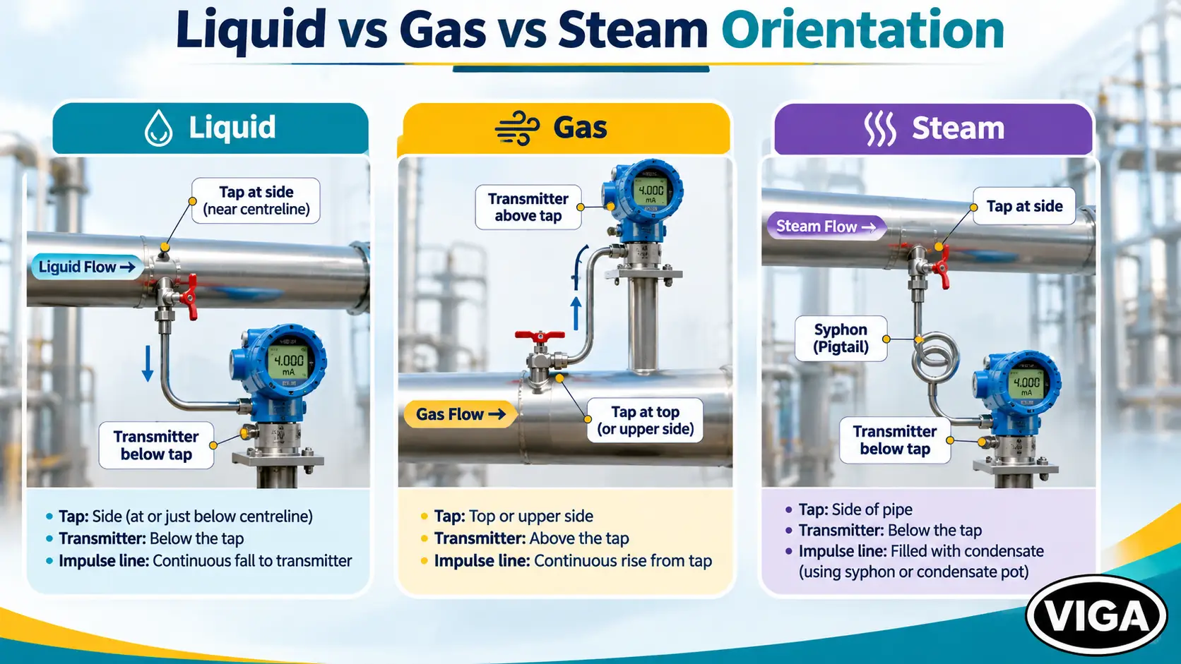
Liquid service. Tap on the side of a horizontal pipe, at or just below the centreline. The bottom of the pipe collects sediment and plugs the tap. The top collects air and vapour. Mount the transmitter below the tap with the line falling towards it, so any bubble that enters climbs back into the pipe.
Gas service. Tap on the top or upper side. Transmitter above the tap. Condensate forming in the line drains back into the process instead of pooling in front of the diaphragm.
Steam service. Tap on the side. Transmitter below the tap. The line fills with condensate, and that water column stands between live steam and the sensor, shielding it from thermal shock. On gauge pressure, a syphon (pigtail) creates the same seal. On differential pressure, condensate pots go at equal elevation and both legs are filled with water before the first block valve opens.
Process Orientation Matrix
| Medium | Tap Position | Transmitter Position | Engineering Rationale | Required Hardware / Accessory |
|---|---|---|---|---|
| Liquid | Side of pipe, at or just below centreline | Below the tap | Entrained gas rises back into the pipe; leg stays liquid-full | Vent valve on manifold; diaphragm seal for slurry or viscous media |
| Gas | Top or upper side of pipe | Above the tap | Condensate drains back to process; leg stays dry | Drain pot at any unavoidable low point |
| Steam | Side of pipe | Below the tap | Condensate seal protects the sensor from steam temperature and thermal shock | Syphon (gauge) or matched condensate pots (DP) |
Where the plant layout forces the wrong side, the fallback is a vent at every high point on liquid service and a drain pot at every low point on gas service. It works. It also creates a maintenance task that someone has to remember forever.
Standing liquid head. A transmitter mounted below a liquid tap also feels the liquid column above it:
ΔP = ρ × g × h
For water, ρ = 1000 kg/m³ and g = 9.81 m/s², so each metre of head gives 1000 × 9.81 × 1 = 9,810 Pa, or 0.0981 bar per metre. For other liquids, multiply by specific gravity.
Worked example: a transmitter 2 m below the tap on water service carries 2 × 0.0981 = 0.196 bar of standing head offset. On an oil with SG 0.85, the same 2 m drop gives 2 × 0.0981 × 0.85 = 0.167 bar. On a low-range transmitter, that offset can be a large slice of span, and it is removed with a zero trim at commissioning, never ignored.
Step 2 — Installing the Impulse Line
- Root valve first. Fit it directly at the tap. It isolates the entire impulse run from the process and lets the transmitter and manifold come out later without a shutdown.
- Tubing over small-bore pipe wherever the spec allows. It bends around obstructions with far fewer joints, and every joint deleted is one less leak path.
- Cut clean, deburr every end. A burr left inside the tube bore becomes a chip of metal heading for the diaphragm.
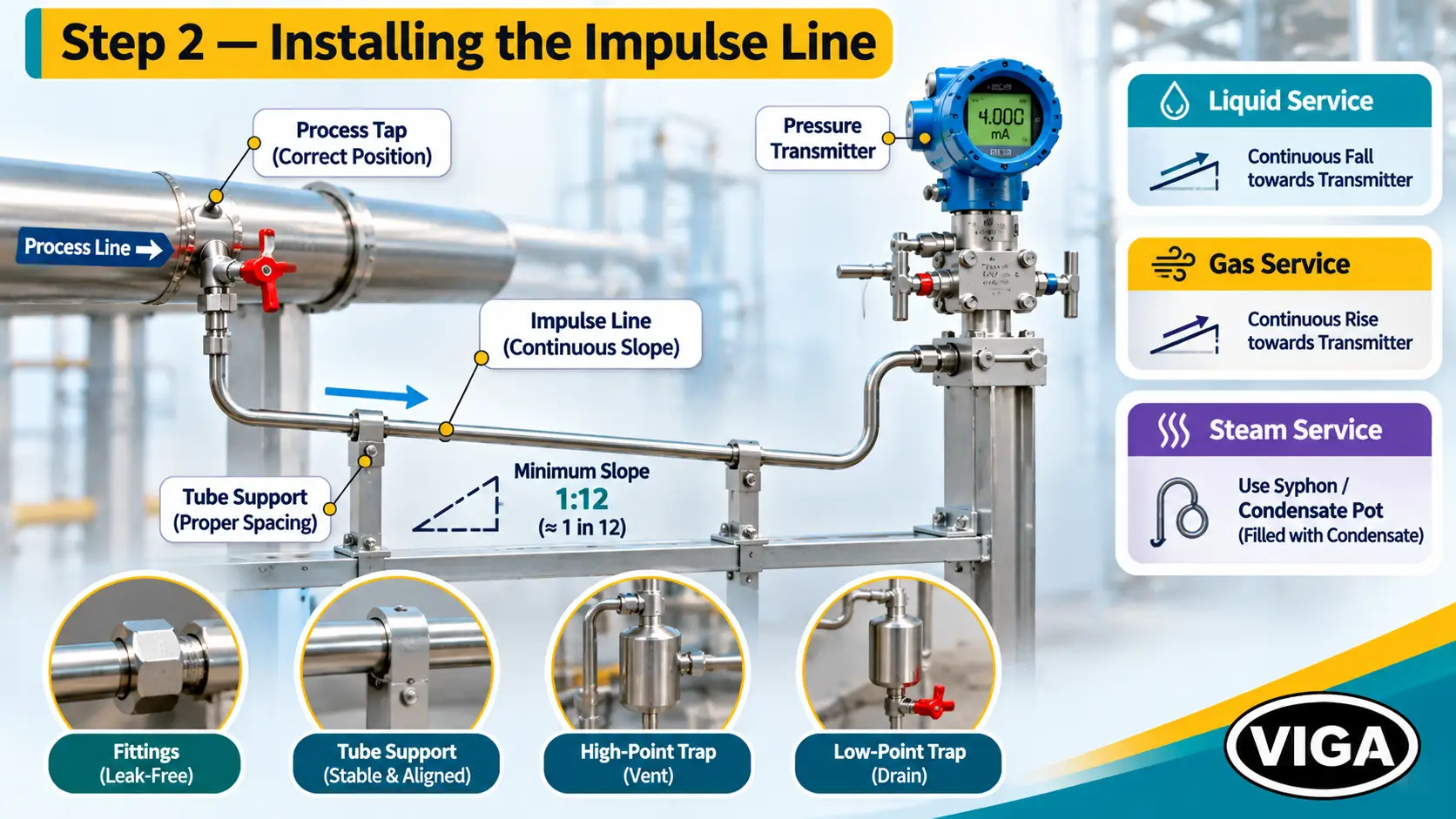
- Slope at 1:12 minimum, roughly 8 cm of fall per metre, falling towards the transmitter on liquid and steam service and rising towards it on gas. No high points in a liquid line, where air collects. No low points in a gas line, where liquid collects. One sag in a gas run is a liquid trap.
- Shortest practical route. Length adds lag, temperature error and more places to plug.
- Run DP legs as a matched pair. Same length, same route, same temperature. A density difference between high and low legs reads as differential pressure.
- Support the tubing at the intervals on the hook-up drawing. The transmitter connection is not a pipe support.
- Blow the line clean before the transmitter goes on. Swarf, mill scale and weld spatter riding down a new line can dent an isolating diaphragm on the first pressurisation.
- Leak-test every fitting. Soap solution or pressure test before commissioning.
Hydro-test warning: When the process line is hydro-tested, the transmitter is isolated at the manifold or removed. Hydro-test pressure routinely exceeds the transmitter’s range, and on a DP cell it arrives on one side only.
Thread sealing. Tapered NPT threads seal on the thread flanks, so PTFE tape or a compatible paste is correct, wrapped with the first thread left bare. Skip that and PTFE shreds into the bore, lodges against the diaphragm, or partially blocks the port. Parallel BSPP (G) threads seal on a bonded washer or O-ring at the face. Tape on a parallel thread does nothing except stop that face seal from seating.
Pulsation and difficult media. Near reciprocating compressors and positive displacement pumps, a pulsation snubber or a needle valve set for damping stops the sensor from absorbing every stroke. For slurries, viscous fluids, corrosive chemicals and hygienic lines, a diaphragm seal keeps the process out of the transmitter entirely.
Step 3 — Mounting the Transmitter & Manifold
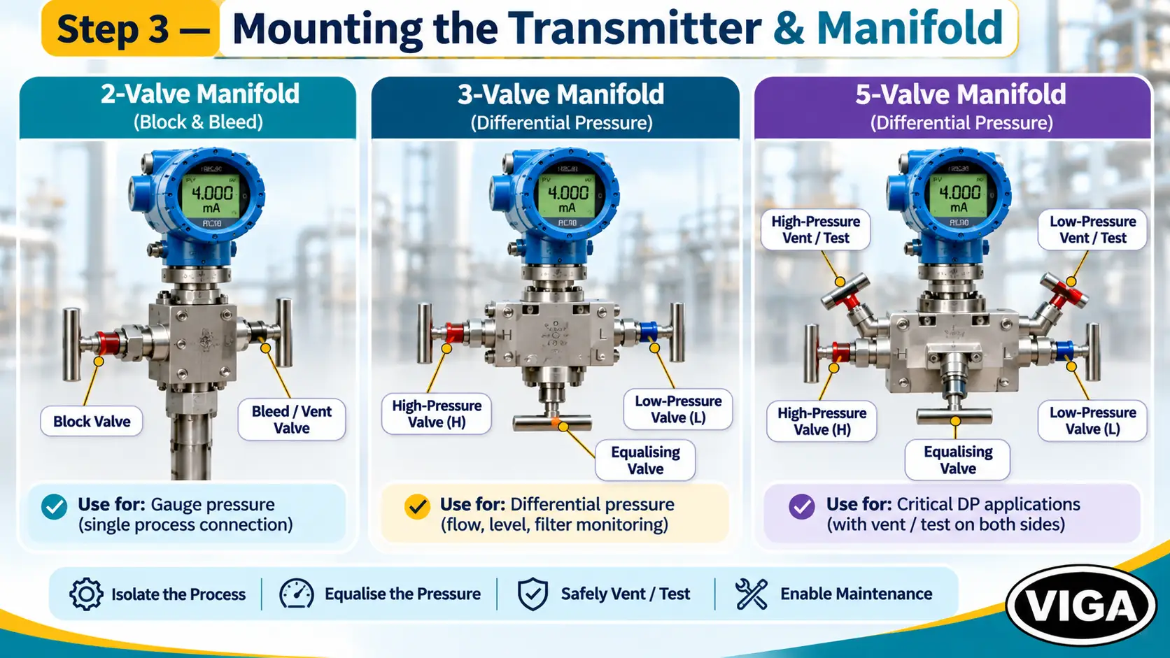
The manifold makes a transmitter serviceable. It isolates, vents, equalises and gives a calibration port without breaking a single impulse fitting.
| Manifold | Valves | Application |
|---|---|---|
| 2-valve block-and-bleed | One block, one bleed/vent | Gauge and absolute pressure |
| 3-valve | Two blocks, one equaliser | Differential pressure: flow, level, filter DP |
| 5-valve | Two blocks, one equaliser, two vent/test | Differential pressure where venting and in-situ testing are frequent, common on gas flow |
Mounting sequence
- Fix the bracket to a 2″ pipe stand or rigid steelwork. Not to vibrating process pipe, unless the assembly is designed for direct mounting.
- Fit the manifold to the transmitter with the correct gaskets or O-rings. Torque the bolts evenly in a cross pattern to the manufacturer’s value. On DP units, confirm H and L match the right impulse legs. On flow, H goes to the upstream tapping.
- Mount the assembly with the display readable and cable entries facing down.
- Rotate the electronics housing only within the manual’s stated limit. Past the stop, the sensor-to-electronics connection can break.
- Connect impulse lines to the manifold, never straight to the transmitter where a manifold is specified.
- Tighten on the process connection hex flats with a backing spanner. Never use the housing as a handle.
- Leave the manifold isolated: blocks closed, and on DP the equaliser open.
3-valve DP manifold: into service
- Confirm equaliser open
- Slowly open the high-side block
- Vent trapped gas from the transmitter body
- Close the equaliser
- Open the low-side block
3-valve DP manifold: out of service
- Close the high-side block
- Open the equaliser
- Close the low-side block
- Vent before removal
Why the sequence matters: A DP cell measures a small difference between two large pressures. With the equaliser open, both sides of the diaphragm see the same static pressure and the differential stays near zero. Open one block valve with the equaliser closed and the other side isolated, and the full line pressure lands on one face of the diaphragm with nothing behind it. A cell ranged for a few hundred millibar of differential can suddenly see full static line pressure as differential. That is one-sided overpressure, and it permanently shifts or ruptures the sensing diaphragm.
Steam and condensate legs: Never leave the equaliser open with both block valves open on a live process. Flow passes from the high leg to the low leg through the manifold and drains the condensate seals the measurement depends on.
Step 4 — Wiring the 4-20mA Loop
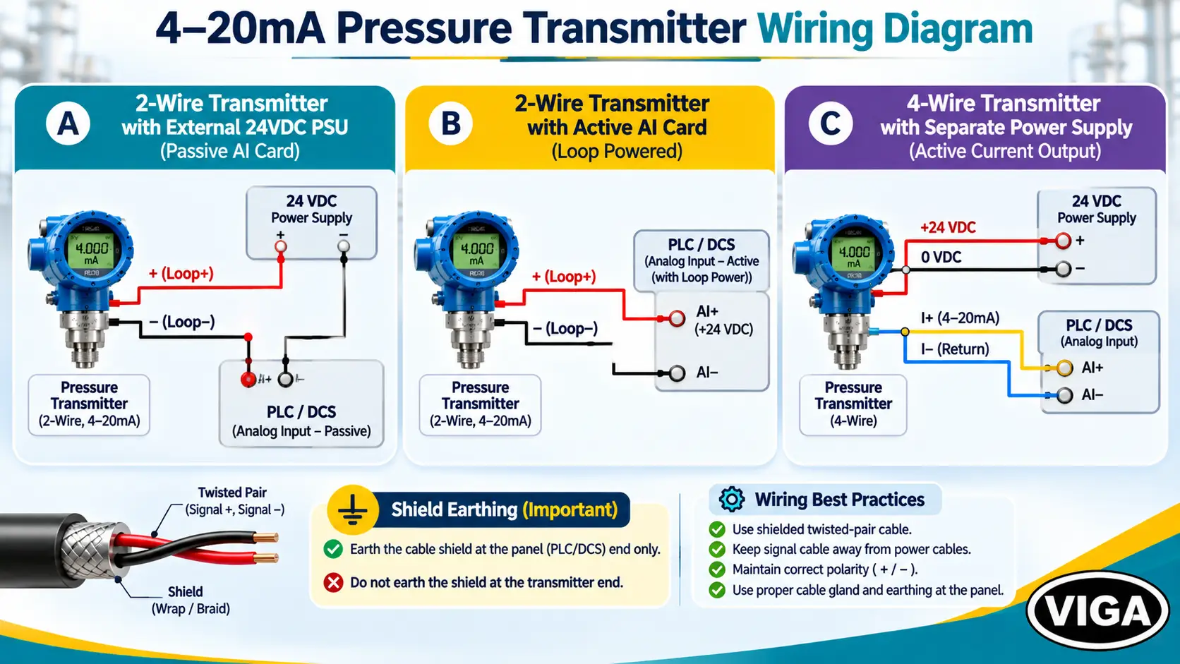
A 4-20mA loop is a series circuit, so the same current flows through every element in it: supply, transmitter, cable, input resistor. The transmitter regulates that current against pressure, 4 mA at LRV, 20 mA at URV.
The 4 mA live zero is deliberate. Zero current means a broken wire or dead supply, never zero pressure. A two-wire transmitter also runs its own electronics on that minimum current.
Two-wire vs four-wire
- Two-wire (loop-powered): two terminals carry both power and signal. The transmitter is passive; something else in the loop must supply voltage.
- Four-wire (separately powered): dedicated power terminals, plus an active output that sources current into a passive input.
Voltage budget. Every two-wire transmitter needs a minimum voltage across its terminals, stated on the datasheet. Size the loop so that minimum survives at the highest current the loop will ever carry, which under NAMUR NE 43 high-alarm conditions is above 21 mA. Using 22 mA covers it:
R_max = (V_supply − V_tx_min) ÷ 0.022 A
Worked example with a 24 VDC supply and a transmitter needing 10.5 V:
R_max = (24 − 10.5) ÷ 0.022 = 13.5 ÷ 0.022 = 613.6 Ω
That 613.6 Ω is the entire budget. A 250 Ω input resistor leaves 363.6 Ω for everything else: the IS barrier or isolator, terminals, and both cores of the cable, so the conductor length counted is twice the route length. Substitute real datasheet values every time.
Cable and shield
- Shielded twisted pair, run separately from power and VFD cables, crossing them at right angles.
- Single-point shield earth: bond the shield at the panel instrument earth bar only. At the field end, clip the shield back and insulate it with heat-shrink. A shield earthed at both ends forms a ground loop, and the result is ground loop hum riding on the signal as a jittery reading.
- Correct glands, certified blanking plugs in unused entries, drip loop below the entry.
- Ferrule and tag both ends. Pull-test every terminated core.
Transmitter wiring diagram
Connecting to PLC/DCS Input
First question at the panel: is the analog input channel passive or active? A passive input measures current but needs a supply somewhere in the loop. An active input supplies the loop voltage itself. The card manual answers it, and many modern cards set this per channel.
Wrong guess, two symptoms. A two-wire transmitter on a passive channel with no external supply gives no current at all. A four-wire transmitter’s active output on an active channel puts two sources head to head.
Then the channel configuration:
- Input type 4-20 mA, not 0-20 mA or voltage.
- Scaling: 4 mA = LRV, 20 mA = URV in engineering units, matching the transmitter exactly. A 0–16 bar transmitter into a 0–10 bar PLC block reads wrong by a fixed ratio across the whole range and looks precisely like a faulty instrument.
- Fault thresholds per NAMUR NE 43: below 3.6 mA or above 21 mA is a device or wiring fault; saturation at about 3.8 mA or 20.5 mA means the process is outside the calibrated range. Alarm the two differently.
In hazardous areas, the loop passes through an IS barrier or galvanic isolator. Entity parameters of transmitter, cable and barrier must be checked against each other, and the barrier’s drop comes out of the voltage budget above.
Step 5 — Powering Up & Configuration
Pre-energisation checks
- Continuity, both cores, end to end
- Polarity at transmitter, marshalling and card
- Insulation resistance test with the transmitter disconnected
- Reconnect, close terminal covers, energise
Equipment protection: Insulation testers apply high DC voltage. Megger a cable with the transmitter still landed and the test can destroy the electronics.
With the transmitter vented (gauge) or equalised (DP), the output should sit near 4 mA. Measure through the transmitter’s test terminals where fitted, otherwise with a mA meter in series at marshalling.
Configuration against the datasheet
- Tag and descriptor
- LRV, URV and engineering units
- Damping: enough to settle process noise, not enough to hide a real excursion
- Transfer function: linear for pressure. For DP flow, square-root extraction happens in the transmitter or in the PLC. Never both.
- Failure alarm direction (upscale or downscale), agreed with the control engineer
- Display settings
Dual square-root bug: Square root applied in the transmitter and again in the PLC turns a flow reading into the square root of the square root of DP. At low flow the error is enormous, and it is invisible on a single spot check at full flow.
HART Setup If Applicable
HART superimposes a digital signal on the 4-20 mA current, so configuration travels on the same two wires. The loop needs between 230 Ω and 1100 Ω of resistance for HART to communicate, with 250 Ω the standard choice. If the input card’s internal resistance falls short, add a series resistor and count its drop in the voltage budget.
Connect the communicator across the loop resistor or directly across the transmitter terminals. Read the device identity, write the tag and long tag, confirm range, units, damping and alarm direction, then enable write protection at the end of commissioning. Save the configuration record against the tag.
Multidrop trap: For a standard point-to-point 4-20 mA loop, the polling address is 0. On older HART devices, any non-zero address switches the transmitter into multidrop mode and parks the output at a fixed 4 mA regardless of pressure. On HART 6 and 7 devices, loop current mode is a separate setting that can be disabled by mistake. Symptom in both cases: the communicator shows a live pressure, the PLC shows a dead 4 mA.
Step 6 — Calibration & Verification
Transmitter calibration after install proves the installed loop. The sensor already left the factory calibrated; what has changed is its orientation, its head, its wiring and its scaling.
Two adjustments, routinely confused:
| Adjustment | What it changes | When to use it |
|---|---|---|
| Zero trim (sensor trim) | Corrects the sensor reading for mounting position and standing liquid head | At commissioning, in the final installed position, with true zero applied |
| Re-ranging | Changes which pressures map to 4 mA (LRV) and 20 mA (URV) | When the process range itself changes |
Zero-trim with true zero applied: a gauge transmitter vented to atmosphere through the manifold, a DP transmitter equalised.
Absolute transmitter warning: Never zero-trim an absolute pressure transmitter while it is vented to atmosphere. The trim teaches the sensor that roughly one atmosphere equals zero, and every reading after that carries the error.
5-Point Calibration & Verification Sheet
| % Span | Applied Pressure | Expected Current (mA) | Tolerance Window (±0.05% of span) | Field DCS Reading |
|---|---|---|---|---|
| 0% | LRV | 4.000 | 3.992 – 4.008 | |
| 25% | LRV + 0.25 × span | 8.000 | 7.992 – 8.008 | |
| 50% | LRV + 0.50 × span | 12.000 | 11.992 – 12.008 | |
| 75% | LRV + 0.75 × span | 16.000 | 15.992 – 16.008 | |
| 100% | URV | 20.000 | 19.992 – 20.008 |
The tolerance column is worked for a transmitter specified at ±0.05% of span: 16 mA × 0.0005 = ±0.008 mA. Replace it with the accuracy on the actual datasheet or the plant’s quality procedure, and remember the reference gauge’s own uncertainty must be tighter than the window being tested.
Run the five points ascending, then descending. A reading that differs at the same pressure depending on direction is hysteresis, and it usually points to a mechanical problem: a damaged diaphragm, a sticking seal or a partly blocked port.
For HART devices, a loop test follows. The communicator forces the output to fixed currents, typically 4, 12 and 20 mA, and the control room confirms matching engineering values on the DCS. That proves wiring, scaling and alarm handling independently of the sensor.
Then return to service using the manifold sequence from Step 3, open slowly, recheck every fitting under pressure, and compare the live value against a local gauge on the same line. Record as-found and as-left values and close the loop sheet. The method behind reference standards and test points is covered further in the guide on how to calibrate a pressure gauge.
Common Installation Mistakes to Avoid
- Wrong side of the tap. Liquid transmitter above its tap: trapped gas. Gas transmitter below its tap: pooled condensate. Both give an offset that wanders with temperature and never trims out cleanly.
- Dips and humps. A sag in a gas line holds liquid. A hump in a liquid line holds air.
- Shield earthed at both ends. Ground loop hum on the signal, usually blamed on the transmitter.
- PTFE on the first thread, or tape on BSPP. Shredded tape in the bore; a face seal that never seats.
- Housing used as a spanner. Broken internal connection, voided warranty.
- Range mismatch between transmitter and PLC. Accurate transmitter, wrong number in the control room.
- Square root applied twice on DP flow.
- Manifold opened out of sequence. One-sided static overpressure on a low-range DP cell.
- Transmitter left in during hydro-test.
- Megger with the transmitter landed.
- Zero trim on an absolute transmitter at atmosphere.
- Non-zero HART address on a point-to-point loop, output frozen at 4 mA.
- Cable entry facing up, no drip loop. Monsoon water in the terminal compartment.
FAQ: Transmitter Installation
Q1. Should a pressure transmitter be mounted above or below the tap?
Below the tap on liquid and steam service; above the tap on gas service. Below keeps a liquid leg full, because bubbles rise back into the pipe, and keeps a condensate seal in front of the sensor on steam. Above lets condensate drain back into a gas line instead of collecting at the diaphragm.
Q2. Does a 4-20mA pressure transmitter need a separate power supply?
A two-wire transmitter takes its power from the loop current, so the loop needs a DC source: an external 24 VDC supply or an active analog input card. A four-wire transmitter needs its own dedicated power supply in addition to the signal pair.
Q3. What is the cable distance limit for a 4-20mA transmitter?
No fixed length applies. The limit is the voltage budget: total loop resistance, including both cable cores, the input resistor and any barrier, must leave the transmitter at or above its minimum terminal voltage at 22 mA. HART adds a second limit set by cable capacitance and resistance on long runs.
Q4. Does a pressure transmitter need calibration after installation?
The sensor arrives calibrated, but the installed loop still needs proving. A zero trim corrects for mounting position and standing liquid head, and a 5-point check from 4 to 20 mA confirms wiring and PLC scaling. Absolute transmitters are never zero-trimmed at atmospheric pressure.
Instrument Sourcing & Factory Integration Standards (Delhi NCR / North India)
A correct installation starts with a correct specification. Before a purchase order goes out, the transmitter and its hook-up hardware should be defined as a matched assembly, not as separate line items picked on price.
Transmitter specification
- Range chosen so normal operating pressure sits comfortably within span, with LRV and URV stated
- Wetted materials compatible with the process medium
- Process connection that matches the manifold (thread form stated explicitly: NPT or BSPP)
- Output and protocol: 4-20 mA, with or without HART
- Accuracy class stated, since it sets the tolerance window at commissioning
- Ex certification where the area classification requires it
- Manufacturer models in this class include WIKA A-10 and S-20 general-purpose transmitters and the Mass PT series
Manifold and accessories
- 2-valve, 3-valve or 5-valve manifold to suit gauge or DP service; Mass 2VM, 3VM and 5VM manifolds cover these configurations
- Diaphragm seals for slurry, viscous, corrosive or hygienic media
- Pulsation snubbers or damping needle valves near reciprocating equipment
- Syphons or condensate pots on steam
Documentation to request with supply
- Manufacturer’s calibration certificate for each transmitter, with traceability stated (in India, certificates from NABL-accredited laboratories carry that traceability)
- Material certificates for wetted parts where the plant QA requires them
- Ex certificates for hazardous-area units
Procurement through an authorised channel matters for one reason above all: the manufacturer’s warranty and documentation chain only holds for genuine product supplied through that channel.
VIGA (Vinod Gautam Sales), Chawri Bazar, Delhi, is an Authorized Distributor of WIKA and Mass instrumentation, supporting manufacturing hubs across Faridabad, Okhla, Wazirpur, Noida, Gurgaon and Baddi. For specification support on transmitters, manifolds and installation accessories: +91-11-43025959, +91-11-41582888, [email protected].