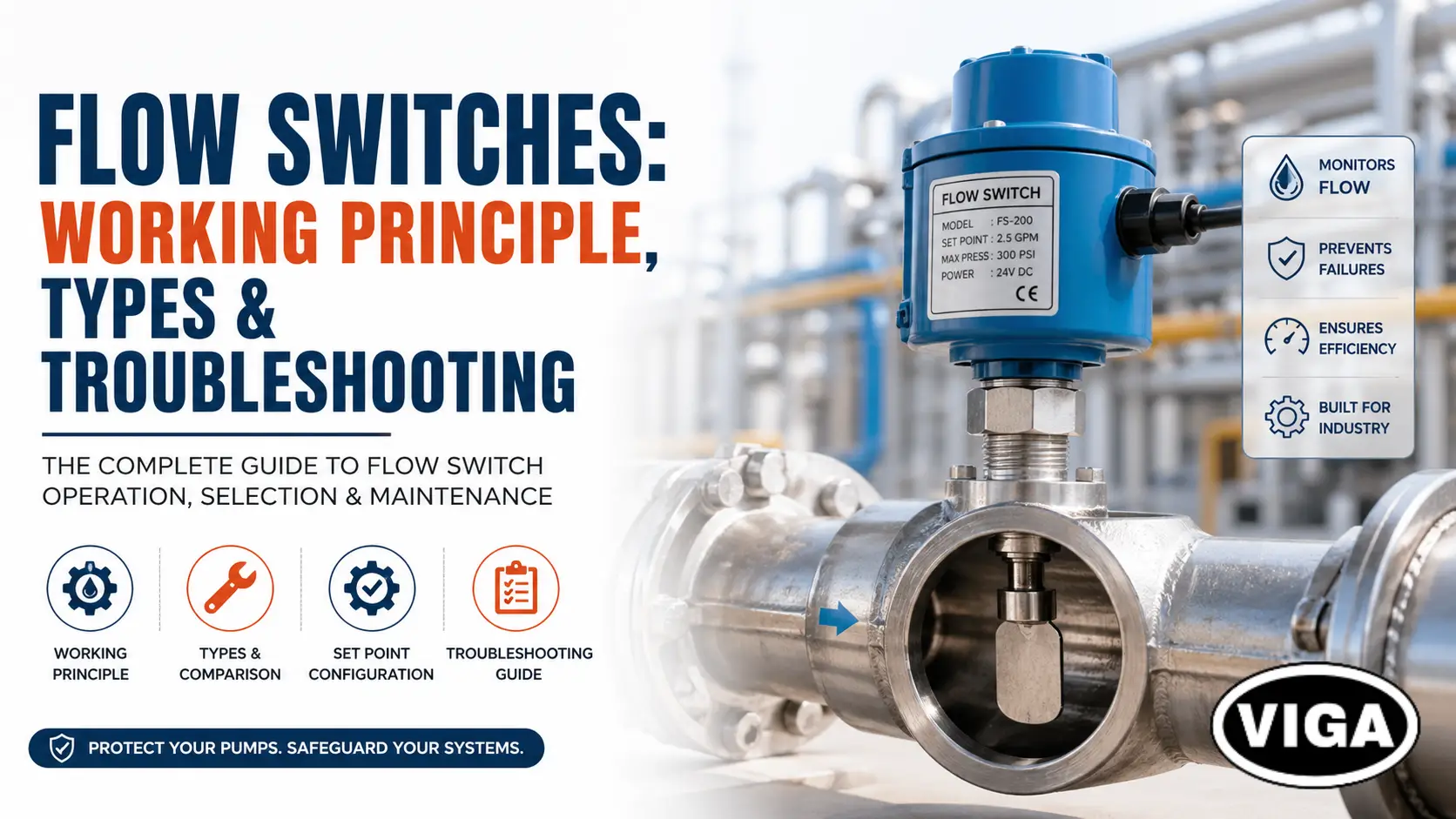
Flow Switches: Working Principle, Types & Troubleshooting
What exactly is a flow switch? Think of it as a pipeline’s emergency brake. It’s a mechanical or electronic safety guard bolted directly into your piping to watch the movement of liquids or gases. It doesn’t just watch, though. It physically stops disasters. If the flow rate dips too low or spikes too high, it snaps an electrical contact shut. Instantly. Pumps power down. Alarms blast. Backup systems kick in.
Quick Technical Summary:
- Core Job: A physical fail-safe tracking liquid or air speed.
- The Big Difference: Sensors give you continuous analog numbers. Switches just give you a hard Yes or No (a binary dry contact closure).
- Best For: HVAC chillers, centrifugal pumps, and fire protection systems.
Pump cavitation is an expensive mistake. In power infrastructure, pneumatic automation, or heavy manufacturing plants, Industrial pipelines do not fail politely; they fail violently.
If you manage heavy infrastructure, you know that relying solely on software to monitor your piping is a gamble. You need physical, mechanical fail-safes. Flow switches provide exactly that. They are binary. They do not care about trend lines or data logs. They care about one thing: is the fluid moving fast enough to keep this equipment safe? If the answer is no, they kill the circuit.
This guide breaks down the exact mechanics, engineering tolerances, and field applications of industrial flow switches. We will strip away the marketing fluff and look at how these devices actually perform under pressure, heat, and heavy industrial use.
The Raw Physics: How a Flow Switch Actually Works
You don’t need a PhD in fluid dynamics to understand the flow switch working principle. It is straight physics. Fluid moving through a confined space generates force. Period. Whether you pump chilled water, heavy crude, or compressed air, that medium hits hard. The switch sits in the pipe for one reason. It catches that exact physical force. Think of it as a violent game of tug-of-war. You have fluid velocity ripping down the line against the stiff resistance of an internal mechanical spring.
The Actuation Sequence: What Happens Inside
Grab a standard mechanical paddle switch off the shelf. Thread it into a pipe tee. That metal fin hangs dead-center in the flow stream. Then, the pump kicks on.
- The Impact: Rushing liquid literally crashes into the flat surface of the paddle.
- The Push: That raw kinetic energy physically forces the metal fin forward.
- Fighting Back: Pushing the paddle isn’t easy. The water has to fight an internal tension spring sitting inside the main housing.
- The Breakpoint: The paddle finally moves far enough. An internal lever trips a microswitch.
- The Flip: The electrical state instantly reverses. A normally open (NO) circuit snaps closed.
The second the flow stops, or drops below the velocity required to hold that spring back, the spring takes over. It aggressively snaps the paddle back to zero. The electrical circuit breaks. The pump shuts off. Disaster is averted.
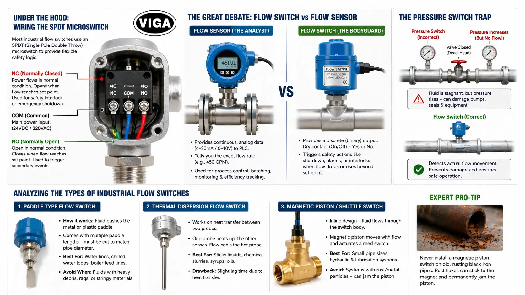
Under the Hood: Wiring the SPDT Microswitch
Open up a heavy-duty industrial unit. You will almost always stare at a Single Pole Double Throw (SPDT) contact block. That tiny block is your best friend. It lets field engineers wire the safety logic exactly how the plant needs it.
- Common (COM): Your main voltage feed. Think 24VDC or standard 220VAC.
- Normally Open (NO): The circuit sits dead. Nothing happens until the fluid hits your required speed. Use this to trigger secondary events. Example: You only want your chemical dosing pump injecting chlorine when the main water line actually flows.
- Normally Closed (NC): Power runs straight through it right now. Once flow hits the set point, the contact snaps open. Power dies. This is your emergency kill switch. Example: You run an electric immersion heater. If the water stops, that heater will ignite. The NC contact kills the heater the exact second the water stalls.
The Great Debate: Flow Switch vs Flow Sensor
Stop mixing these up. They do totally different jobs. Too many buyers waste budget purchasing the wrong unit because they think “sensor” and “switch” are interchangeable terms. They are not.
Flow Sensor (The Analyst)
A flow sensor provides continuous, analog data. It outputs a 4-20mA or 0-10V signal to your Programmable Logic Controller (PLC). It tells you, “The system is currently pushing 450 gallons per minute.” It is a diagnostic tool used for process control, batching, and efficiency tracking. If you want to chart water usage over a month, buy a sensor. Instrumentation engineers often see procurement managers make this costly error. Let’s draw a strict line between the two.
Flow Switch (The Bodyguard)
A flow switch is a discrete safety interlock. It provides zero trend data. It simply provides a dry contact closure. Yes or no. On or off. It tells your control panel, “Flow has dropped to a critical 50 gallons per minute; execute an emergency shutdown immediately.”
The Pressure Switch Trap
Another massive mistake in plant design is using a pressure switch instead of a flow switch. A pressure switch measures static force against the pipe wall. If a valve closes dead-head downstream, the pressure inside the pipe will actually spike, satisfying the pressure switch. Meanwhile, the fluid is completely stagnant. If a pump is running in this dead-head condition, it will boil the water inside its own volute and destroy its mechanical seals. A liquid flow switch prevents this because it only triggers on actual movement, not static pressure.
Analyzing the Types of Industrial Flow Switches
You cannot install a cheap plastic switch on a 300 PSI hydraulic line, and you should not waste money on a high-end thermal unit for a basic sump pump. Matching the switch type to the fluid’s physical properties is mandatory.
1. Paddle Type Flow Switch
This is the most common, cost-effective design in the world. It uses a physical fin dropped right into the fluid path.
- How it works: Fluid pushes the metal or plastic paddle.
- The Reality of Sizing: When you buy a paddle switch, it usually comes with three or four different lengths of metal fins in the box. You must literally cut the fin with tin snips to match your pipe diameter. Cut it too short, and the boundary layer of the fluid (which moves slower near the pipe wall) will not have enough force to push it. Leave it too long, and it will scrape against the bottom of the pipe and jam permanently.
- Best For: Standard water lines, large diameter chilled water loops, boiler feed lines.
- Avoid When: The fluid has heavy debris, rags, or stringy materials. The debris will wrap around the paddle and snap it off.
2. Thermal Dispersion Flow Switch
This is high-end electronic monitoring. You get zero physical moving parts hanging in your pipe. None.
- The Mechanics: It runs entirely on heat transfer. The tip drops two probes into the liquid. One probe artificially heats up. The other just reads the normal baseline liquid temperature. Liquid rushes past the hot probe. It steals the heat. Faster flow equals faster cooling. The circuit board calculates that exact temperature drop and fires the relay.
- Where It Wins: Sticky, nasty liquids. Heavy syrups, chemical slurries, or thick oils that would snap a mechanical paddle in half.
- The Drawback: Lag time. Heat transfer takes a second or two. You will deal with slight latency. If your system requires an instant, split-second shutdown, look at a different technology.
3. Magnetic Piston / Shuttle Switch
We usually see this built as an inline flow switch. The unit literally becomes part of the piping run. The entire fluid volume pushes straight through the switch body itself.
- The Mechanics: A tiny, permanent magnet sits inside a metal piston. That piston floats inside a tight brass or stainless steel cylinder. Liquid forces the piston upward against a calibrated spring. When the piston climbs high enough, the magnetic field reaches through the solid metal casing. It snaps a tiny reed switch mounted on the outside.
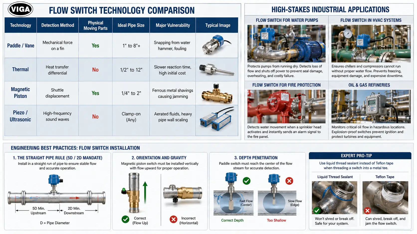
Flow Switch Technology Comparison Table
Use the comparison matrix below to match the correct flow switch technology to your pipeline requirements.
Technology | Detection Method | Physical Moving Parts | Ideal Pipe Size | Major Vulnerability |
Paddle / Vane | Mechanical force on a fin | Yes | 1″ to 8″+ | Snapping from water hammer, fouling |
Thermal | Heat transfer differential | No | 1/2″ to 12″ | Slower reaction time, high initial cost |
Magnetic Piston | Shuttle displacement | Yes | 1/4″ to 2″ | Ferrous metal shavings causing jamming |
Piezo / Ultrasonic | High-frequency sound waves | No | Clamp-on (Any) | Aerated fluids, heavy pipe wall scaling |
High-Stakes Industrial Applications
Where are these devices actually deployed? They sit at the heart of nearly every critical infrastructure loop.
Flow Switch for Water Pumps
Centrifugal pumps are incredibly tough, but they have a fatal flaw: they cannot run dry. The liquid they pump acts as the coolant for their internal mechanical seals. If a suction strainer clogs, the pump starves. It spins at 3600 RPM, generating massive frictional heat. Within minutes, the seals melt, the shaft warps, and the motor burns out. A flow switch wired directly into the pump’s motor starter contactor acts as a hard kill switch. No flow? No power.
Flow Switch in HVAC Systems
Walk into any commercial building’s mechanical room, and you will see large chillers. These machines use heavy compressors to cool water for the building’s air conditioning. A flow switch for HVAC is legally mandated by building codes in many jurisdictions. If the chilled water pump trips on an overload, the water inside the chiller stops moving. If the massive compressor keeps running, it will freeze that stagnant water solid in seconds. Ice expands. It will rupture the internal copper tubes, mixing refrigerant with water and destroying a half-million-dollar piece of equipment. The switch ensures the compressor cannot physically engage unless water is flowing.
Flow Switch for Fire Protection System
Fire suppression relies on immediate notification. Sprinkler pipes are always full of pressurized water, but that water does not move. When a fire breaks out and melts the glass bulb on a sprinkler head, the water suddenly rushes out. A highly specialized vane-type flow switch detects this movement. It does not shut anything down; instead, it sends an immediate alarm signal to the building’s main fire panel, which then calls the local fire department and drops the building’s elevators to the ground floor.
Oil & Gas Refineries
In explosive atmospheres, a tiny electrical arc from a standard microswitch will ignite ambient gas fumes. Refineries use explosion-proof flow switches housed in cast-aluminum NEMA 7 enclosures. They monitor lubricating oil flow to massive turbine bearings. If a turbine loses lube oil pressure for even three seconds, the bearings will weld themselves together, causing millions in damages and weeks of plant downtime.
Engineering Best Practices: Flow Switch Installation
You can buy the best industrial flow switch on the market, but if you install it poorly, it will fail constantly. Pipe hydraulics are chaotic.
1. The Straight Pipe Rule (The 5D / 2D Mandate)
Fluid does not flow smoothly right after it turns a corner. As water exits a 90-degree elbow, it spins in a vortex. If you stick a mechanical paddle into that vortex, the paddle will bounce wildly, causing the electrical contacts to chatter. You must install the switch in a straight run of pipe. The golden rule is a minimum of 5 times the pipe diameter of straight run upstream of the switch, and 2 times the pipe diameter downstream.
2. Orientation and Gravity
A magnetic piston switch must be installed vertically, with the fluid flowing upward. It relies on the physical weight of the piston to drop back down when the flow stops. If you install it horizontally, the piston will just lie there, and the switch will never reset.
3. Depth Penetration
For paddle switches, you must thread the device deep enough so the fin hits the center of the flow stream. The fluid near the inner walls of the pipe moves much slower due to friction (the boundary layer). If your paddle only penetrates an inch into a six-inch pipe, it will not register enough force to actuate.
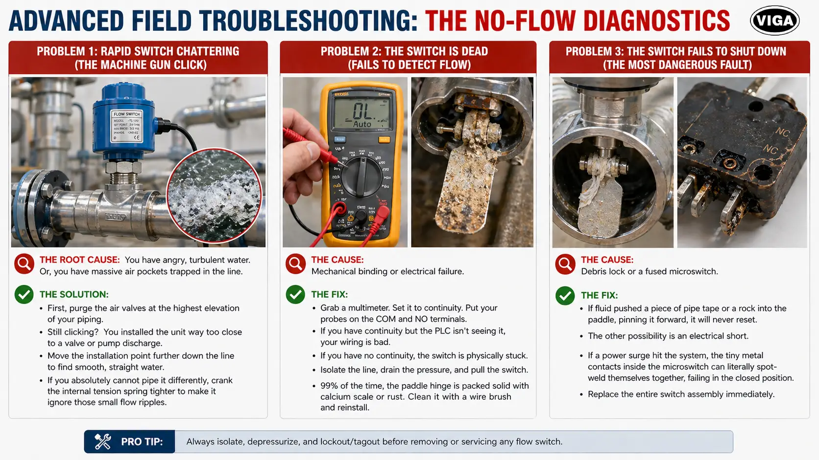
Advanced Field Troubleshooting: The No-Flow Diagnostics
A dead system costs thousands of dollars an hour. When your PLC flashes a “No Flow” fault, you cannot waste time guessing. You need a fast, accurate diagnosis on the factory floor right now.
Problem 1: Rapid Switch Chattering (The Machine Gun Click)
You walk up to the panel. The relay sounds like it is firing on full auto.
- The Root Cause: You have angry, turbulent water. Or, you have massive air pockets trapped in the line.
- The Solution: First, purge the air valves at the highest elevation of your piping. Still clicking? You installed the unit way too close to a valve or pump discharge. Grab your pipe cutter. You have to physically move the installation point further down the line to find smooth, straight water. If you absolutely cannot pipe it differently, crank the internal tension spring tighter to make it ignore those small flow ripples.
Problem 2: The Switch is Dead (Fails to Detect Flow)
The pump is running. Water is moving. The switch does not care.
- The Cause: Mechanical binding or electrical failure.
- The Fix: First, grab a multimeter. Set it to continuity. Put your probes on the COM and NO terminals. If you have continuity but the PLC isn’t seeing it, your wiring is bad. If you have no continuity, the switch is physically stuck. Isolate the line, drain the pressure, and pull the switch. 99% of the time, the paddle hinge is packed solid with calcium scale or rust. Clean it with a wire brush and reinstall.
Problem 3: The Switch Fails to Shut Down (The Most Dangerous Fault)
The pump stopped, but the switch is still telling the computer that water is flowing.
- The Cause: Debris lock or a fused microswitch.
- The Fix: If the fluid pushed a piece of pipe tape or a rock into the paddle, pinning it forward, it will never reset. The other possibility is an electrical short. If a power surge hit the system, the tiny metal contacts inside the microswitch can literally spot-weld themselves together, failing in the closed position. You must replace the entire switch assembly immediately.
Final Thoughts on Instrumentation Strategy
Industrial automation relies entirely on accurate field data. A control system is incredibly stupid; it only knows what its sensors and switches tell it. By deploying the correct type of flow detection—whether that is a rugged magnetic shuttle for hydraulics or a sensitive thermal probe for chemical lines—you strip away the guesswork. Protect your pumps. Guard your chillers. Understand the hydraulics of your specific pipeline, calculate your velocity, and install your flow switches exactly according to the straight-pipe engineering rules. When things go wrong in a mechanical room, a well-calibrated switch is the only thing standing between a minor tripped alarm and a catastrophic equipment failure.
Frequently Asked Questions (FAQ)
Q1. How do I verify if my flow switch is actually working?
A: You perform a physical flow test. Turn the system on and verify the switch contacts close using a multimeter set to continuity. Then, slowly close a manual isolation valve downstream to restrict the flow. Watch the multimeter. The moment the flow drops below your calculated set point, the continuity should break. If it does not, your spring tension is too loose or the switch is mechanically bound.
Q2. Can I use a water flow switch for an air or gas line?
A: Absolutely not. Water is dense; it carries massive kinetic energy at low speeds. Air is highly compressible and lacks the physical density to push a heavy liquid paddle. If you need to monitor ductwork or compressed air, you must buy a specific pneumatic flow switch, often called a “sail switch,” which features a very large, lightweight fin designed to catch fast-moving air.
Q3. Why do industrial flow switches have both Normally Open (NO) and Normally Closed (NC) contacts?
A: It provides total control over fail-safe logic. Use the NO contact if you want an external device (like an alarm bell or a chemical doser) to activate only when the main pipeline is actively flowing. Use the NC contact as a safety interlock to kill power to a heater or a pump the exact moment the fluid stops moving.
Q4. What does the NEMA rating on a flow switch housing mean?
A: The National Electrical Manufacturers Association (NEMA) rating dictates what environment the switch enclosure can survive. NEMA 1 is strictly for clean, indoor dry use. NEMA 4X means it is watertight, dust-tight, and highly corrosion-resistant (perfect for washdown areas). NEMA 7 means it is explosion-proof, designed specifically to contain internal electrical sparks in hazardous oil and gas environments.
Q5. How frequently should an industrial flow switch be recalibrated or cleaned?
A: In clean, closed-loop systems like chilled water HVAC circuits, inspect them annually. In open-loop systems like cooling towers, where biological growth and mineral scaling are aggressive, they should be pulled out of the pipe, physically inspected, wire-brushed, and mechanically tested every six months to prevent the paddle hinge from seizing.
About the Author
Written by a Senior Industrial Automation Specialist with over 15+ years of hands-on field experience. No textbook theory. Just raw, factory-floor reality. Having commissioned fluid safety interlocks for high-pressure refineries and diagnosed complex HVAC chilled water loops, they specialize in heavy instrumentation and process control. They build the physical fail-safes that keep million-dollar infrastructure from melting down.