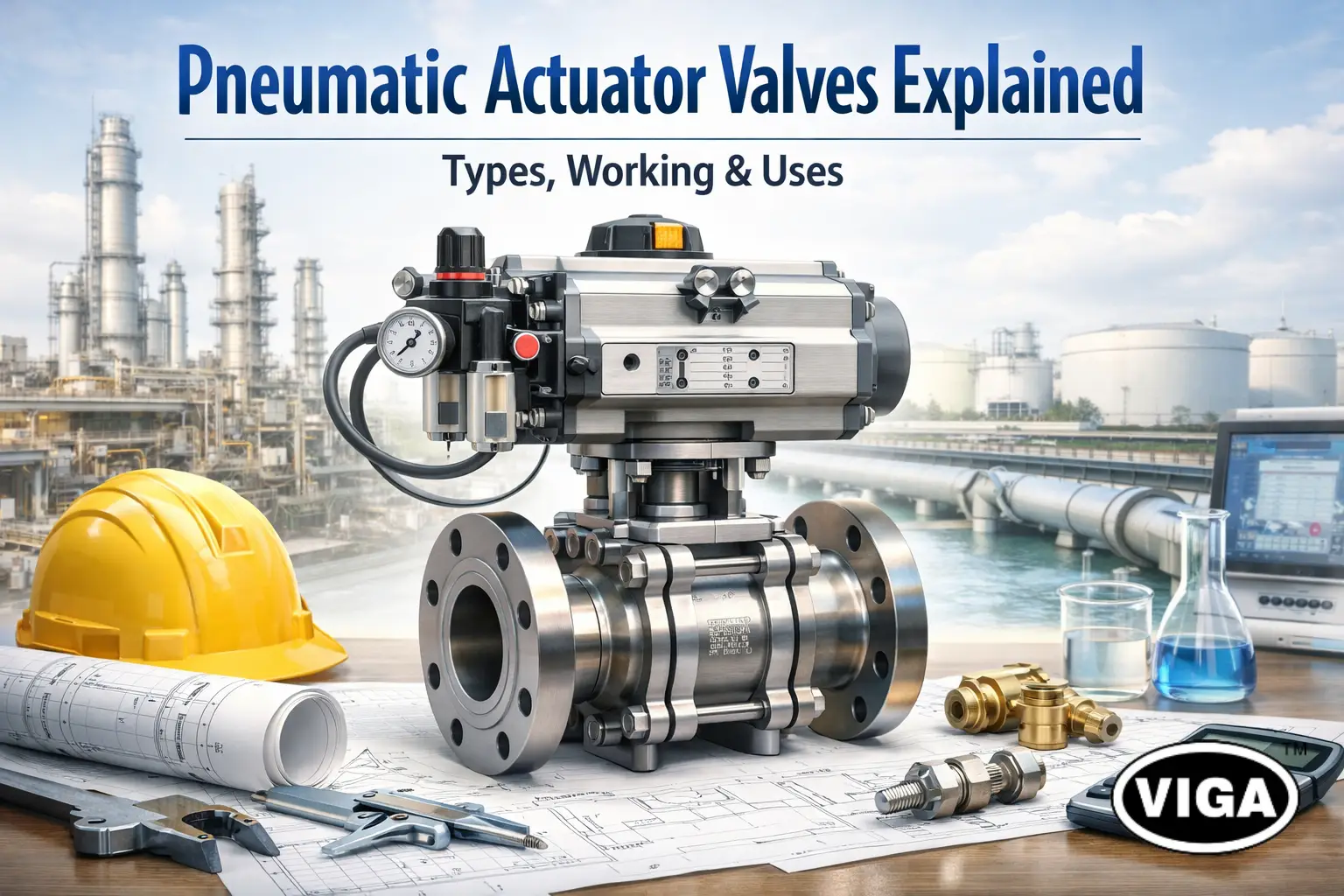
Pneumatics Actuator Valves Explained | Types, Working & Uses
From Switch to Motion — How Pneumatic Actuator Valves Bring Automation Alive!
A control signal traveling down a copper wire is just information. It has no muscle. It cannot stop thousands of gallons of water rushing through a treatment plant or shut down a high-pressure steam line in a fraction of a second. To turn that low-voltage data into physical action, industrial automation relies on the brute force of compressed air.
Pneumatics actuator valves act as the conversion point between the digital control logic of a PLC and the heavy mechanical reality of piping systems. While electric servos grab the headlines for precision in robotics, the process industries—Oil & Gas, Chemical, Water, and Food Processing—run almost entirely on pneumatic actuation.
This preference isn’t about nostalgia. It is about physics. Compressed air systems provide a density of force, speed of response, and inherent safety that electrical systems struggle to match at scale. For the engineer or plant manager, understanding these components is not just about knowing how to open a pipe; it is about understanding the primary safeguard between efficient production and operational failure.
This technical guide dissects the mechanics of pneumatic valve automation, from the torque curves of scotch yoke actuators to the critical sizing calculations required to prevent stall conditions in the field.
What Are Pneumatics Actuator Valves?
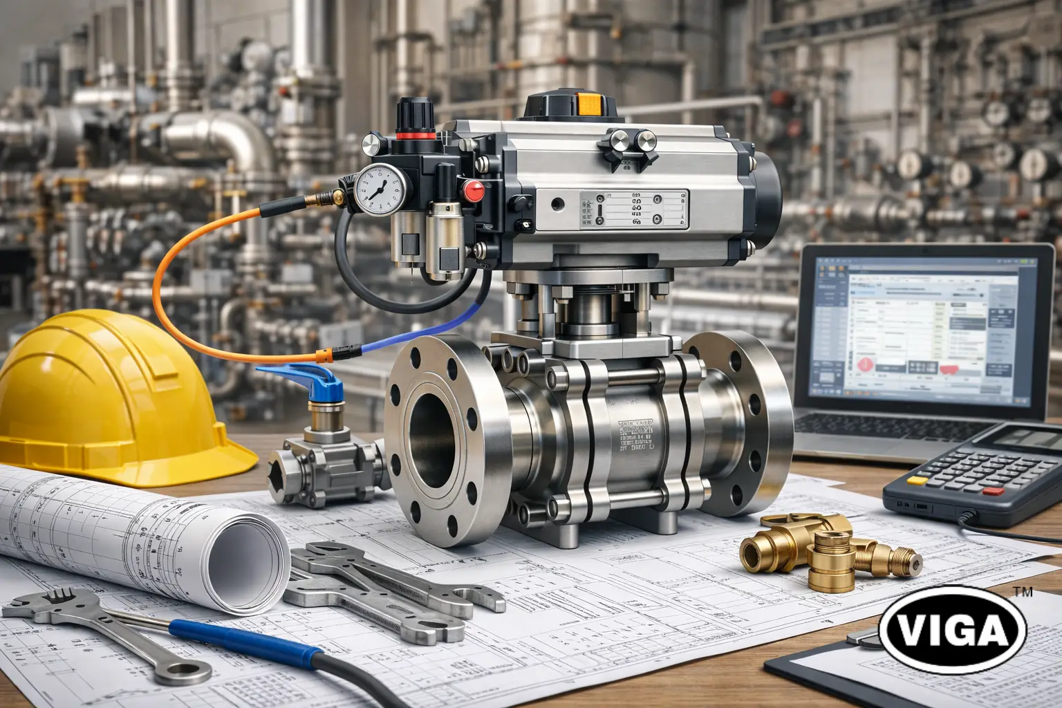
Technically, there is no single component called a “pneumatic actuator valve.” It is an assembly—a marriage of three distinct pieces of hardware that must be compatible to function.
- The Valve Body: The wetted part that controls the media (Ball, Butterfly, Globe, or Gate).
- The Pneumatic Actuator: The aluminum or steel engine that sits on top, converting air pressure into torque (rotary) or thrust (linear).
- The Mounting Hardware: A critical, often overlooked link. This includes the mounting bracket and the drive coupling. These must strictly adhere to ISO 5211 standards to ensure the actuator turns the valve stem rather than shearing it off.
When these three act in concert, driven by a pilot signal, they form the automated unit. Unlike a manual valve requiring an operator’s physical presence, or a solenoid valve which is limited to small diameters (typically under 2 inches), a pneumatic actuator valve system uses the facility’s “fourth utility”—compressed air—to drive large industrial loads with high reliability.
The system scales effectively. The same 80 PSI air supply can actuate a tiny 1/2-inch sampling valve or a massive 48-inch pipeline shut-off valve; the only difference is the surface area of the piston inside the actuator.
How Pneumatics Actuator Valves Work (Step-by-Step)
The operating principle relies on the relationship: Force = Pressure × Area.
Since plant air pressure is generally fixed (typically oscillating between 80 and 100 PSI), manufacturers generate more force by increasing the surface area of the internal pistons.
The sequence of operation typically follows this path:
- Signal Initiation: The PLC (Programmable Logic Controller) or DCS (Distributed Control System) sends a command. This is usually a 24VDC discrete signal (for open/close) or a 4-20mA analog signal (for modulating control).
- Pilot Actuation: This electrical signal energizes a coil in the solenoid valve—commonly a 5/2-way or 3/2-way valve mounted directly to the actuator via a NAMUR interface.
- Air Injection: The solenoid spool shifts, directing air into the actuator’s pressure chamber.
- Energy Conversion: As the chamber fills, air pressure builds against the piston face. Once the force generated exceeds the “breakaway torque” of the valve (plus the friction of the actuator itself), movement begins.
- Motion Transfer:
- In Rack and Pinion designs, the pistons push outward, rotating a central gear.
- In Linear designs, the piston pushes a stem directly down.
- Cycle Completion: As the valve reaches its travel limit (open or closed), the air pressure maintains the position (in double-acting units) or compresses a spring bank (in single-acting units).
Single-Acting (Spring Return) vs. Double-Acting
This is the most critical logic distinction in the specification process.
- Double-Acting (DA): Uses air to open and air to close. It gives the operator control over both strokes and is physically smaller and cheaper because there are no springs taking up internal volume. However, upon air failure, the valve acts unpredictably—it stays where it is, or drifts with flow pressure.
- Single-Acting (Spring Return / SR): Uses air to power the valve in one direction (usually compressing a heavy internal spring). When air supply is cut—intentionally or via accident—the mechanical spring energy drives the valve back to its “fail” position (Fail Close or Fail Open). This mechanical guarantee makes SR actuators the mandatory choice for active safety systems.
Types of Pneumatic Actuator Valves
Not all motion is the same. Engineers categorize these valves based on the mechanical movement required to cycle the flow.
1 Based on Actuator Motion
Rotary Actuators (Quarter-Turn)
Used for ball, butterfly, and plug valves.
- Rack and Pinion: The industry standard for sizes up to 12 inches. It provides linear torque output—meaning the force is consistent throughout the entire 90-degree rotation.
- Scotch Yoke: Designed for heavy-duty torque. The internal mechanics allow the piston to exert maximum leverage at the beginning (break) and end (seat) of the stroke, where valves usually stick. They typically experience a torque dip in the middle of the stroke (“run” torque), which must be calculated carefully against flow velocity.
- Vane Actuators: A niche design involving a paddle that swings in a chamber. They are very compact and use less air but struggle with high-pressure leaks over time.
Linear Actuators (Rising Stem)
Used for globe, gate, and diaphragm valves.
- Pneumatic Diaphragm: Recognizable by the large “mushroom” top. They use a flexible rubber sheet rather than a hard piston. This creates almost zero friction, making them the superior choice for control loops where minute position changes (hysteresis) matter.
- Piston Cylinder: Used for high-thrust applications, such as gate valves or high-pressure globe valves where a rubber diaphragm would burst.
2 Based on Valve Body
Ball Valves
The workhorse of on/off automation. Because the ball “wipes” against the seat during rotation, it handles dirty media well. The torque requirement is moderate but can spike if the valve sits static for weeks (“stiction”).
Butterfly Valves
Common in large water lines and HVAC. They require high torque relative to their size, specifically to unseat the disc from the rubber liner. The “breakaway” torque is critical here; undersized actuators on butterfly valves will result in the valve getting stuck 5 degrees open.
Globe Valves
The standard for flow regulation. The linear plug arrangement creates a torture path for fluid that drops pressure effectively. Pneumatic actuators on globe valves must often be fitted with Positioners—devices that compare the command signal to the physical stem position and adjust air pressure dynamically to hold a precise flow rate.
3 Based on Application Criticality
Shut-down Valves (SDV / ESD)
These are always single-acting/spring-return. In refinery applications, these pneumatic valves act as the circuit breakers of the pipe. If a gas sensor detects a leak, power to the solenoid is cut, and the spring slams the valve shut.
Modulating Control Valves
These valves never just “open” or “close.” They hunt. A PID controller constantly adjusts them to maintain temperature or pressure. Pneumatic diaphragm actuators are preferred here because they handle the constant dithering (minor back-and-forth movement) better than electric gear trains, which would wear out.
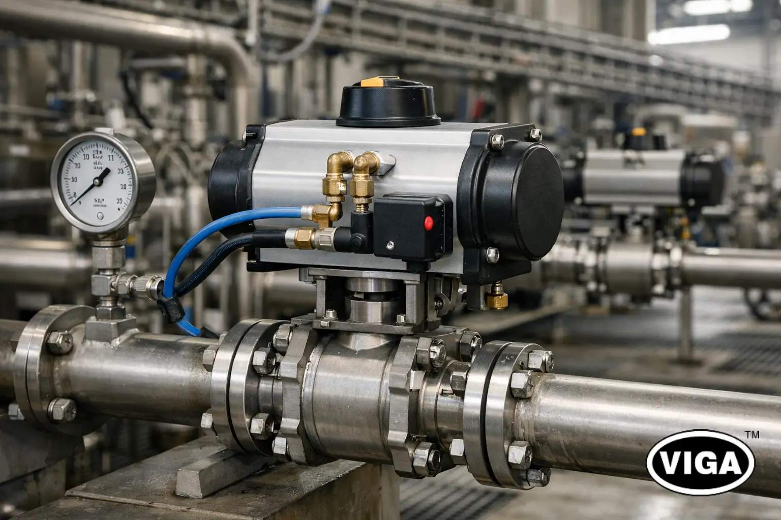
Why Pneumatics Actuator Valves Are Essential in Automation
In a world increasingly dominated by electrical data, the persistence of air-driven mechanics seems anachronistic to outsiders. However, automation professionals prefer pneumatics for tangible reasons.
Operational Safety (Hazardous Locations)
Petrochemical, Paint, and Mining industries operate in volatile atmospheres. An electric motor needs massive, cast-iron “Explosion Proof” (Ex d) housing to prevent internal sparks from igniting external vapors. A pneumatic actuator creates no sparks. It runs on cold air. This makes them inherently compliant with ATEX, IECEx, and NEC hazardous location standards, usually at 50% of the cost of an equivalent electric actuator.
Duty Cycle Durability
An electric actuator creates heat every time the motor engages. If you ask an electric valve to cycle every 30 seconds, it will eventually trip a thermal overload or burn its windings. Pneumatic actuators generate zero heat during operation. They can cycle once a month or ten times a minute continuously without degradation.
Speed
A spring-return pneumatic actuator can close a sizable process valve in 500 milliseconds. This rapid response is mandatory for safety interlocks. Achieving this speed with an electric motor would require a massive drivetrain and capacitor banks, making the unit significantly larger and more expensive.
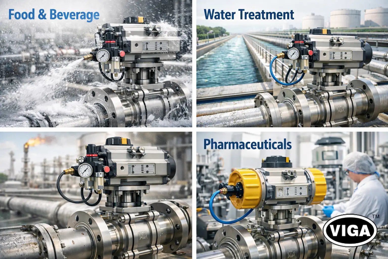
Industrial Applications of Pneumatics Actuator Valves
Context dictates the specification. Here is how different industries leverage pneumatic motion:
Food & Beverage: The Washdown Reality
Factories processing dairy or sauces undergo aggressive high-pressure chemical cleaning daily. Electrical components hate water; even IP67 or IP68 ratings fail eventually. Pneumatic actuators—particularly clean-design stainless steel or techno polymer units—are waterproof by design. As long as the exhaust port is shielded, they can be blasted with caustic foam without failure.
Water Treatment: The Distance Problem
A large municipal water plant might have filter beds 500 yards from the control room. Running heavy-gauge copper power cable to hundreds of 24V or 110V electric actuators causes significant voltage drop problems. Running inexpensive plastic poly-tubing for air signals is cheaper and immune to electrical interference.
Oil & Gas: Remote Operations
In pipeline applications, electricity may not exist. Operators often use “Gas-over-Oil” or direct high-pressure pneumatic actuators driven by the sweet gas directly from the pipeline. The pressurized gas itself becomes the power source for the valve that controls the pipeline.
Pharmaceuticals: Precision Dosing
Bio-reactors require extremely precise control of steam for sterilization. Pneumatic diaphragm valves (hygienic zero-dead-leg designs) fitted with electro-pneumatic positioners can control flow curves to within 0.5% accuracy, ensuring batches aren’t ruined by temperature fluctuations.
Pneumatics Actuator Valves vs Other Actuation Technologies
The “Actuator Triangle” is a tradeoff between Force, Speed, and Precision.
Pneumatic vs Electric Actuation
- Electric wins on: Positional accuracy and complex data feedback. If you need a valve to be exactly 43.5% open and provide torque logs, go electric.
- Pneumatic wins on: Initial cost (CAPEX), simplicity of maintenance (OPEX), speed of operation, and fail-safe mechanical options. A jammed pneumatic actuator just stalls; a jammed electric actuator destroys its gearbox or motor.
Pneumatic vs Hydraulic Actuation
- Hydraulic: Used only when forces are massive. Hydraulic oil is incompressible, meaning it holds rigid position better and delivers torque figures in the hundreds of thousands of Nm. However, hydraulics leak oil, creating environmental hazards.
- Pneumatic: Air is compressible, which makes the motion slightly “softer.” If the valve sticks, the air compresses before the valve jumps (stick-slip). However, a leak in a pneumatic system simply vents nitrogen and oxygen back into the room—clean and safe.
How to Select the Right Pneumatics Actuator Valve
Sizing is the area where most mistakes happen. An undersized actuator is a useless paperweight; an oversized actuator damages the valve stem. The process must follow a logical calculation.
Determining Valve Torque
Consult the valve manufacturer’s torque sheet, but treat it as a baseline only. This “bench torque” is measured with clean water at room temperature.
- Application Multiplier (Safety Factor):
- Clean Liquids (Water/Oils): Add 20%.
- Dirty/Viscous Slurry: Add 40%–50%.
- Dry Granules/Powders: Add 75%–100%.
Available Air Supply
This is the “Silent Killer” of projects. An actuator might generate 100 Nm of torque at 80 PSI. But what happens at 3:00 PM when the plant consumes more air and header pressure drops to 60 PSI?
- Golden Rule: Size the actuator based on the minimum reliable air pressure (usually 60 or 70 PSI / 4 to 5 Bar), not the compressor room setting.
Sizing for Spring Return
With Single-Acting actuators, you have two weak points.
- Air Stroke: The air must overcome the spring force AND the valve friction to open.
- Spring Stroke: Upon failure, the spring alone must overcome valve friction to close it.
- You must verify that the “Spring End Torque” (the force left in the relaxed spring) is still higher than the valve closing torque.
Component Material
If installed outdoors in a coastal environment or inside a corrosive chemical room, standard anodized aluminum bodies will oxidize and pit within a year. In these scenarios, epoxy-coated or full 316 Stainless Steel actuators are non-negotiable investments.
Common Problems & Troubleshooting
Pneumatic systems are robust, but they provide clear signals when they are distressed.
Air Leakage from Exhaust
If air blows out of the exhaust port when the valve is holding a position, the internal piston seals or O-rings have failed. Air is bypassing the piston head. This is usually caused by wear or abrasive particles in the air supply.
Slow Operation
If a valve that usually snaps shut suddenly drifts slowly, check the exhaust silencers/mufflers. These bronze sintered filters clog with dust over time, creating back-pressure that prevents the actuator from venting air. Clean or replace the silencers immediately.
The “Popping” Valve
If the valve does not move initially and then bangs open with a loud noise, it is suffering from stiction (static friction). The actuator may be slightly undersized, requiring pressure to build up to a critical point before “breaking” the hold. This damages valve seats and stems over time.
Maintenance Best Practices
The lifespan of a pneumatic actuator is measured in millions of cycles, provided one condition is met: Clean, Dry Air.
Instrument Air Quality
Water is the enemy. If water condenses inside the actuator, it washes away the factory grease. Without lubrication, the O-rings chafe against the aluminum cylinder wall, leading to failure.
- Install point-of-use FRLs (Filter, Regulator) upstream of critical valves.
- Ensure plant dryers are maintaining a dew point well below ambient temperature.
Seal Replacement
Actuators are serviceable items. Manufacturers sell “Soft Kits” containing replacement O-rings, guides, and grease.
- Predictive Check: In high-criticality applications, perform a “Partial Stroke Test” periodically. Move the valve 10% and verify smooth operation without interrupting flow.
Lubrication Protocol
Be cautious with “lubricators” (oil-misting devices). Most modern actuators come pre-packed with lifetime synthetic grease. Injecting cheap mineral oil into the air line can wash out this high-performance grease and eventually degrade the seals. Unless the manufacturer specifies “lubricated air,” use clean, dry air.
Future of Pneumatic Actuator Valves
While the mechanical principle remains unchanged from the 1900s, the “brains” sitting on top of the actuator are entering the Industry 4.0 era.
Smart Positioners and Digital Twins
Modern valve positioners do more than modulate flow; they analyze the valve’s health. They monitor “Valve Signature” curves. If the amount of pressure required to move the valve increases by 5% over six months, the smart positioner alerts the asset management system that friction is increasing (potentially seal wear or debris buildup). This allows maintenance to fix the valve during a planned shutdown rather than facing an emergency failure at 2 AM.
Energy Efficiency
Compressed air is expensive to generate. Old “flapper-nozzle” positioners bled air constantly, even when the valve was steady. New Piezo-electric technology allows for “zero-bleed” control, where the pilot valve consumes air only when the actuator actually needs to move, significantly cutting plant energy bills.
FAQs
Q1. What are pneumatic actuator valves used for?
They are used to automate flow control in industrial pipes, replacing manual handles with air-driven mechanisms that allow for remote operation, automated sequencing, and rapid emergency shutdowns.
Q2. Difference between pneumatic and electric actuator valves?
Pneumatic valves use compressed air and are faster, simpler, and explosion-proof by design. Electric valves use motors, offering higher precision and better data feedback, but are slower and more expensive to install in hazardous areas.
Q3. Are pneumatic actuator valves safe in explosive environments?
Yes. Since they operate using inert air pressure and contain no internal ignition source (like electrical arcing brushes), they are the standard choice for “Ex” zones (Explosive Atmospheres) such as oil refineries and grain silos.
Q4. How long do pneumatic actuators last?
With clean, dry air supply, a high-quality pneumatic actuator is typically rated for 1 million cycles. However, water or dirt in the air line can destroy the seals within months.
Q5. What pressure is required?
The industry standard is 80 PSI (5.5 Bar). While actuators can function as low as 40 PSI or as high as 120 PSI, torque output changes linearly with pressure. Lower pressure always results in less torque.
Conclusion
The “click-hiss” sound of a pneumatic actuator valve is the heartbeat of modern industry. From the pharmaceutical labs purifying vaccines to the oil pipelines crossing continents, these assemblies perform the heavy lifting of automation.
They persist against high-tech electric competitors because they are mechanically elegant: huge force, tiny footprint, and intrinsically safe operation. For the buyer or engineer, the key to success lies not just in buying a valve, but in calculating the complete load—torque, safety factors, and air quality—to ensure that when the controller sends the signal, the physics delivers the motion.


