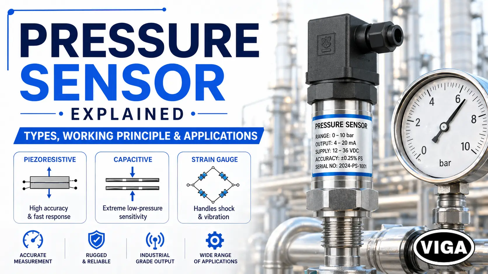
Pressure Sensor Explained: Types, Working Principle & Applications
A pressure sensor detects physical force from liquids or gases and translates it into an electrical signal (such as a 4-20mA loop). In industrial automation, these instruments are critical for controlling valves, preventing pump cavitation, and monitoring flow rates via Programmable Logic Controllers (PLCs) and Variable Frequency Drives (VFDs).
Specifying the wrong sensor type or output signal can result in control system failures, costly downtime, or catastrophic equipment damage. This guide breaks down the core working principles, technologies (piezoresistive, capacitive, strain gauge), and exact specifications required for harsh manufacturing environments.
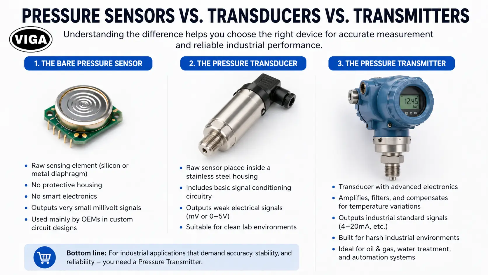
Terminology: Pressure Sensors vs. Transducers vs. Transmitters
The industry uses a lot of terms interchangeably. This creates massive confusion. When someone on the floor yells that they need a new “pressure sensor,” they usually mean something else. Let’s clarify the hardware.
1. The Bare Pressure Sensor
This is just the raw sensing element. It is a tiny piece of silicon or a bare metal diaphragm. It has no protective housing. It has no smart electronics. If you buy just a “sensor,” you are usually an OEM building your own circuit boards.
2. The Pressure Transducer
Take that raw sensor. Put it inside a stainless steel housing. Add a basic circuit board. Now you have a transducer. It outputs a very weak electrical signal—usually raw millivolts (mV) or a low-level voltage like 0-5V. These are fine for clean laboratories. They are terrible for noisy factory floors.
3. The Pressure Transmitter
This is the heavy artillery. It is a transducer packed with advanced amplification electronics. It takes that tiny millivolt signal, cleans it up, compensates for temperature shifts, and boosts it into an industrial-grade signal like a 4-20mA current loop.
When you are buying hardware for an oil rig, a water treatment plant, or an automated assembly line, you are buying a transmitter. Period.
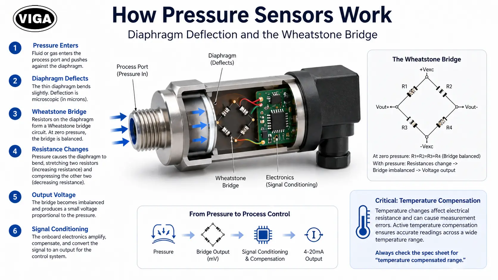
How Pressure Sensors Work: Diaphragm Deflection and the Wheatstone Bridge
So, how does physical water pressure turn into numbers on a computer screen? It comes down to one simple concept: microscopic bending.
Every industrial pressure sensor relies on a sensing element. Usually, this is a very thin diaphragm. Think of it like the skin of a drum. Fluid or gas enters the process port of the sensor and pushes against this diaphragm.
The diaphragm bends.
We are not talking about massive movement here. The deflection is microscopic. It is measured in microns. But that tiny flex is all we need.
Attached to the back of this diaphragm is an electrical circuit, almost always configured as a Wheatstone bridge. This is a diamond-shaped circuit made of four resistors. When the diaphragm is perfectly flat (zero pressure), the electrical resistance is perfectly balanced.
When the fluid pushes the diaphragm, it bends the resistors. Stretching a resistor makes it longer and thinner, which increases its electrical resistance. Compressing it decreases the resistance.
This mechanical stress imbalances the Wheatstone bridge. The bridge then spits out a tiny voltage drop. The harder the fluid pushes, the more the diaphragm bends, the more the resistance changes, and the higher the voltage output becomes. The onboard microprocessor reads this exact voltage, runs it through some math, and sends a clean signal to your control panel.
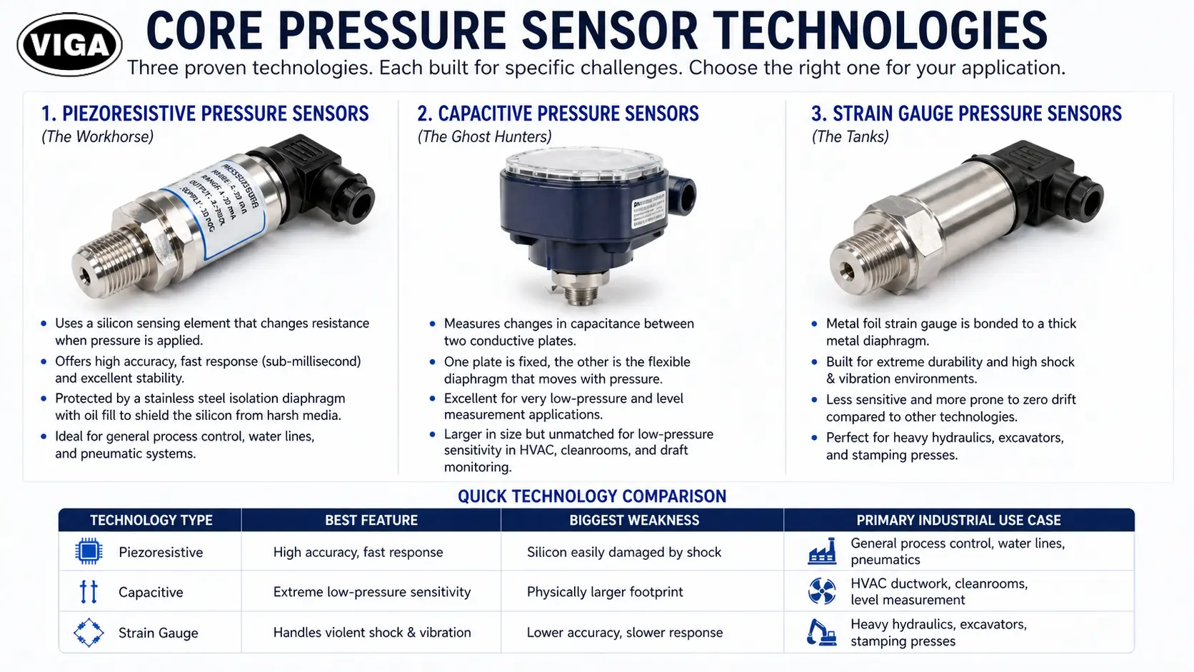
Core Pressure Sensor Technologies
You cannot use one type of sensor for every job. The internal mechanics dictate where the device survives and where it dies. Here are the three technologies that actually matter.
1. Piezoresistive Pressure Sensors (The Workhorse)
Piezoresistive sensors are the standard workhorse for general process control and water lines. Instead of bonded metal resistors, these utilize a solid piece of silicon. Bending the silicon alters its atomic structure and electrical conductivity, providing incredibly fast sub-millisecond response times and high accuracy.
However, bare silicon degrades rapidly when exposed to water or harsh chemicals. To prevent failure, industrial models utilize a stainless steel isolation diaphragm filled with non-compressible transfer oil to protect the silicon element while maintaining measurement accuracy.
2. Capacitive Pressure Sensors (The Ghost Hunters)
Capacitive sensors ignore electrical resistance completely. They measure electrical capacitance.
Inside the housing, there are two conductive plates. One is fixed in place. The other plate is the flexible diaphragm. There is a tiny gap between them. When pressure pushes the flexible plate closer to the fixed plate, the capacitance of the circuit increases.
While capacitive sensors are physically bulkier than other options, they offer extreme low-pressure sensitivity. They can easily measure fractions of an inch of water column, making them unmatched for monitoring precise draft pressures inside industrial chimneys or tracking delicate airflow in HVAC ductwork.
3. Strain Gauge Pressure Sensors (The Tanks)
This is older technology, but it refuses to die. A metal foil pattern is bonded directly to a thick metal diaphragm. It relies on pure brute force.
While this technology is less sensitive and more prone to zero drift over long periods, it offers unmatched brute-force durability. If you put a piezoresistive silicon sensor on a heavy stamping press, the violent shockwaves will shatter the chip into dust. A bonded foil strain gauge, however, effortlessly absorbs extreme shock and high-impact vibration without failing.
Quick Technology Comparison
Technology Type | Best Feature | Biggest Weakness | Primary Industrial Use Case |
Piezoresistive | High accuracy, fast response | Silicon easily damaged by shock | General process control, water lines, pneumatics |
Capacitive | Extreme low-pressure sensitivity | Physically larger footprint | HVAC ductwork, cleanrooms, level measurement |
Strain Gauge | Handles violent shock & vibration | Lower accuracy, slower response | Heavy hydraulics, excavators, stamping presses |
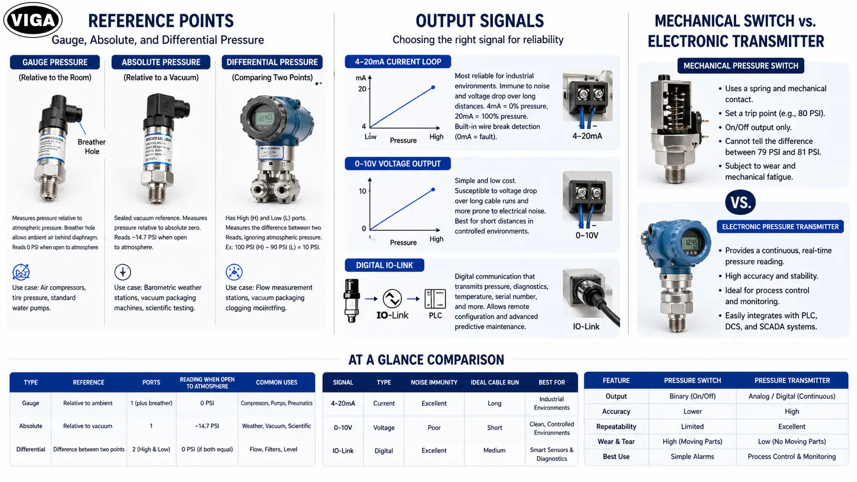
Reference Points: Gauge, Absolute, and Differential Pressure
You have selected your technology. Now you need to define your reference point. Pressure is just a measurement of force compared to something else. What is your “something else”?
Gauge Pressure Sensor (Relative to the Room)
This is the standard. A gauge sensor measures pressure relative to whatever the atmospheric pressure is in the room right now.
Look at the back of a gauge sensor. You will find a tiny breather hole. That hole lets ambient air sit behind the sensing diaphragm. If you hold this sensor in your hand, it reads zero. If a storm rolls in and the atmospheric pressure drops, the sensor adjusts automatically and still reads zero.
- Use case: Air compressors, tire pressure, standard water pumps.
Absolute Pressure Sensor (Relative to a Vacuum)
These sensors do not care about the weather. They do not care if you are at sea level or on top of a mountain.
The space behind the sensing diaphragm is completely pumped free of air and permanently sealed under a hard vacuum. It measures pressure relative to absolute zero. If you hold this sensor in your hand, it will read about 14.7 PSI (the actual weight of the Earth’s atmosphere pushing down on the diaphragm).
- Use case: Barometric weather stations, vacuum packaging machines, specialized scientific testing.
Differential Pressure Sensor (Comparing Two Points)
Differential sensors have two physical threaded ports. A High side and a Low side. They measure the exact difference between the two, completely ignoring the room’s atmospheric pressure.
If you put 100 PSI into the High port and 90 PSI into the Low port, the sensor outputs a reading of 10 PSI.
- Use case: We use these constantly to measure flow rates across an orifice plate or to monitor how clogged an industrial filter is getting.
Output Signals: 4-20mA, 0-10V, and IO-Link
Getting an accurate physical measurement is useless if the signal degrades before it reaches the control panel. Your output signal dictates your reliability.
The 4-20mA Current Loop
If you are running cables across a factory floor, you use 4-20mA. Accept no substitutes.
Instead of varying voltage, the transmitter varies the current in the wire. Zero pressure equals 4 milliamps. Maximum pressure equals 20 milliamps.
Why start at 4mA? Because it acts as a built-in safety net. If a forklift runs over your cable and severs it, the current drops to 0mA. Your PLC sees 0mA and instantly flags a “Wire Break” alarm. If the sensor outputted 0mA for zero pressure, your PLC wouldn’t know if the pipe was empty or if the cable was cut.
Current loops are incredibly resistant to electromagnetic interference (EMI). You can run a 4-20mA cable right past a massive industrial motor, and the signal stays rock solid.
0-10V Voltage Output
These vary the voltage. Zero pressure is 0 Volts. Max pressure is 10 Volts.
They are cheaper, but they have a fatal flaw: wire resistance. If you run a voltage signal across 500 feet of cable, the natural resistance of the copper wire will cause a voltage drop. The sensor might send 10V, but the PLC only receives 9.2V. Suddenly, your system thinks the pressure is lower than it actually is. They also pick up EMI like an antenna. Keep these inside clean control cabinets with very short cable runs.
Digital IO-Link
Digital sensors do not just send a raw electrical value. They send actual data packets. A smart sensor using IO-Link can tell the PLC its exact pressure, its internal temperature, its serial number, and whether its internal diaphragm is starting to fail. You can even log into the PLC and remotely change the sensor’s measurement range without walking out to the machine.
Mechanical Pressure Switches vs. Electronic Pressure Transmitters
I see this mistake constantly. A plant manager wants to upgrade a system, so they swap out an old mechanical pressure switch for a new electronic pressure sensor, but they don’t change the PLC logic.
- Pressure Switch: A dumb mechanical spring. You crank a screw to set a trip point (like 80 PSI). When the pipe hits 80 PSI, the spring snaps and closes an electrical contact. It is binary. On or off. It cannot tell you if the pressure is 79 PSI or 81 PSI.
- Pressure Sensor: Gives you a continuous, live feed of the exact pressure at all times.
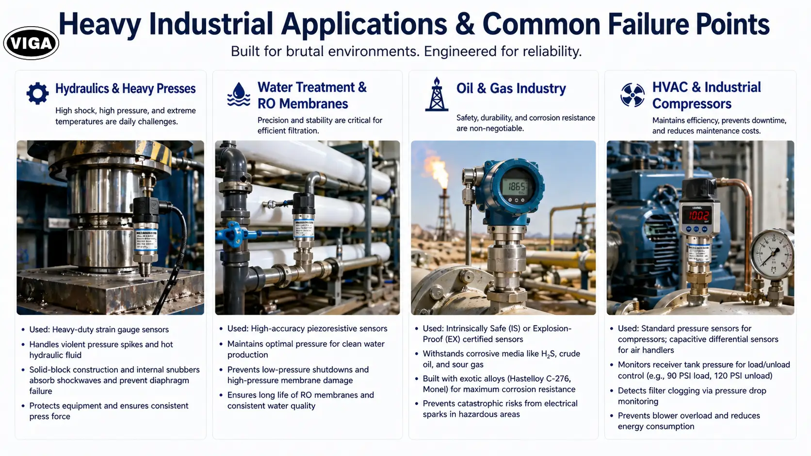
Heavy Industrial Applications and Common Failure Points
You don’t buy these devices to sit on a shelf. You buy them to do brutal work. Here is how different industries push them to the limit.
Hydraulics & Heavy Presses
Imagine a massive metal stamping press. It requires exact force to shape steel without tearing it. We use heavy-duty strain gauge sensors here. The pressure spikes are violent. The hydraulic fluid is hot. A standard sensor would get its isolation diaphragm ripped apart in a week. We need solid-block construction and internal snubbers to handle the shockwaves.
Water Treatment & RO Membranes
Reverse Osmosis (RO) plants use high pressure to force dirty water through microscopic filters. If the pressure is too low, the plant stops producing clean water. If the pressure spikes, the expensive membranes tear. We use highly accurate piezoresistive sensors here to maintain the absolute perfect balance.
The Oil & Gas Industry
You cannot put a standard sensor on a natural gas pipeline. A single electrical spark from the sensor’s circuit board could level the facility. Oil and gas require Intrinsically Safe (IS) or Explosion-Proof (EX) certified sensors. Furthermore, raw crude oil and sour gas contain hydrogen sulfide. It eats standard 316 stainless steel for breakfast. We have to spec sensors built from exotic alloys like Hastelloy C-276 or Monel.
HVAC and Industrial Compressors
Air compressors are the heartbeat of a manufacturing plant. A pressure sensor for compressors monitors the receiver tank. When plant pressure drops to 90 PSI, it tells the compressor to load. When it hits 120 PSI, it tells it to unload. In the building’s ductwork, we use ultra-low differential capacitive sensors to monitor air handlers. When a filter gets loaded with dust, the pressure drop across it increases. The sensor sees this and alerts maintenance before the blower motor burns out trying to push air through a brick wall of dirt.
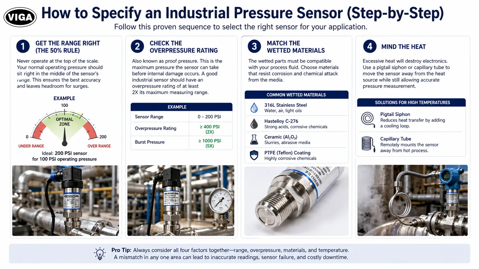
How to Specify an Industrial Pressure Sensor (Step-by-Step)
Stop looking at the price first. Look at your process conditions. Follow this exact sequence to specify your hardware.
Step 1: Get the Range Right (The 50% Rule)
Never buy a sensor where your normal operating pressure is at the absolute top of the scale. If your pipe runs at 100 PSI all day, do not buy a 100 PSI sensor. Buy a 200 PSI sensor. You want your normal operating pressure to sit right in the middle of the sensor’s range. This gives you the best accuracy and leaves plenty of headroom for unexpected surges.
Step 2: Check the Overpressure Rating
Also known as proof pressure. This is how much pressure the sensor can take before the internal diaphragm permanently bends and ruins the calibration. A good industrial sensor should have an overpressure rating of at least 2X its maximum measuring range.
Step 3: Match the Wetted Materials
What exactly is touching the sensor? Tap water? Hydraulic oil? Nitric acid? The “wetted parts” must survive the chemical. Standard 316L stainless is great for water and light oils. For aggressive chemicals, you might need a ceramic sensing element or a PTFE (Teflon) coating.
Step 4: Mind the Heat
Electronics melt. If you thread a transmitter directly into a 400-degree steam line, it will die in minutes. If your process is excessively hot, you must install a pigtail siphon or a capillary tube to physically move the sensor away from the heat source while still allowing the fluid pressure to reach it.
Field Troubleshooting Guide: Zero Drift, Clogs, and Water Hammer
Sensors fail. But they rarely just “die” for no reason. Usually, the process kills them. Here is how to diagnose a lying sensor on the floor.
- Zero Drift (Reading pressure on an empty pipe): This indicates the sensor was over-torqued during installation or suffered a severe pressure spike that tweaked the metal housing. Solution: Vent the pipe to atmospheric pressure and ‘tare’ the reading using the physical zero-potentiometer or your PLC software. If it drifts again, the diaphragm is permanently compromised and the unit must be replaced.
- Sluggish Response Time (Plugged Port): Heavy sludge, rust, or calcium buildup can pack into the tiny hole leading to the diaphragm. Solution: Pull the sensor and soak the port in a mild solvent. Never shove a screwdriver or paperclip into the hole, as this will instantly puncture the diaphragm. For naturally dirty processes, switch to a ‘flush mount’ sensor where the diaphragm sits flat against the pipe wall to prevent material buildup entirely.
- Sensor Blowout on a Water Line (Water Hammer): When a large pneumatic valve slams shut instantly, kinetic energy bounces back through the pipe, creating a microsecond supersonic shockwave that easily exceeds the sensor’s burst pressure. Solution: Install a pressure snubber. This tiny threaded fitting contains a porous metal filter that acts as a hydraulic shock absorber, allowing gradual pressure through while blocking violent, high-speed shockwaves.
Final Thoughts on Plant Instrumentation
You can have the most advanced PLC logic in the world, backed by millions of dollars of automated valves and massive industrial pumps. None of it matters if the raw data feeding that system is garbage.
Specifying a pressure sensor isn’t about finding the cheapest hardware to plug a hole in a pipe. It is about understanding the physics of your specific process. It is about anticipating the vibration, the heat, and the chemical exposure.
Protect the wetted parts. Specify the correct electrical output to fight off factory noise. Stop buying hardware that barely meets your maximum pressure specs. When you over-engineer the measurement point, you eliminate the late-night maintenance calls. You stop chasing ghost alarms in the PLC. You get absolute, uncompromised control over your industrial process.
Frequently Asked Questions (FAQ)
Q: Can a standard pressure sensor measure a negative vacuum?
A: No. A standard gauge pressure sensor only reads positive pressure above the ambient room pressure. If you pull a vacuum on it, it will just read zero. If you need to measure both vacuum and positive pressure on the same line, you must specifically order a “compound” pressure sensor (e.g., scaled from -14.7 PSI to +100 PSI).
Q: What is the difference between accuracy and repeatability?
A: Accuracy is how close the sensor’s reading is to the actual, true physical pressure in the pipe. Repeatability is whether the sensor outputs the exact same electrical signal every single time it hits that specific pressure, regardless of accuracy. In industrial process control, high repeatability is often far more valuable than perfect accuracy.
Q: Why does my 4-20mA signal read 3.5mA right now?
A: That is not a glitch; it is an active fault code. Many high-end smart transmitters are programmed with NAMUR NE43 standard diagnostics. If the internal circuitry detects a catastrophic failure (like a ruptured diaphragm or a dead memory chip), it intentionally drops the signal below the standard 4mA baseline (usually to 3.5mA or 3.6mA) to explicitly warn the PLC that the sensor is broken, not just reading zero pressure.
Q: How tightly should I torque a new pressure sensor into a pipe?
A: Hand-tighten it, then give it a 1/2 to 3/4 turn with a wrench. Never over-tighten it. Over-torquing physically distorts the stainless steel housing. That distortion transfers directly into the delicate internal sensing bridge, causing massive, permanent zero-drift before you even turn the machine on.
Q: Can I use thread seal tape (Teflon tape) on the sensor threads?
A: Yes, but be incredibly careful. If you let a stray piece of Teflon tape hang over the edge of the thread, the fluid flow can tear it off and jam it directly into the sensor’s process port. This will instantly blind the sensor. Leave the bottom two threads completely bare when applying tape.