


Pressure Switch Installation Guide: Wiring, Setpoint Adjustment & Commissioning
The short answer: mount the switch on an isolable, vibration-free tapping. Wire the contact that matches what must happen as pressure rises: NC to stop a load, NO to start one or raise an alarm. Set the trip point against a calibrated reference gauge, open the differential wide enough to prevent short-cycling, then cycle the pressure slowly three times and record where the switch actually operates.
Wire the contacts wrong and the pump runs when it should stop. Set the deadband too tight and the compressor clicks on and off until the contactor gives up. Pressure switch installation looks like a twenty-minute job, but almost every callback after a new install traces back to three decisions: which contact was wired, where the setpoint sits, and how wide the differential was left.
This guide covers how to install a pressure switch the way commissioning engineers do it on site: mounting, how to wire a pressure switch for NO or NC duty, pressure switch setpoint setting, deadband adjustment, and a test routine that proves the switch before handover. A pressure switch wiring diagram for the two most common duties, stopping a compressor and raising a high-pressure alarm, is included in Step 2.
Understanding NO and NC Contacts First
Most mechanical pressure switches carry a single-pole, double-throw (SPDT) microswitch with three terminals: Common (C or COM), Normally Open (NO) and Normally Closed (NC). Every wiring decision that follows depends on reading those labels correctly.
The word “normally” causes more wrong installations than any other term on the label. It describes the contact with no pressure applied, or with pressure below the setpoint, exactly as the switch sits on the shelf. It does not describe the plant’s normal running condition. A compressor switch spends most of its working life at pressure, so its “normally closed” contact is often open while the plant is running perfectly.
| Terminal pair | Pressure below setpoint (switch at rest) | Pressure above setpoint (switch actuated) | Typical duty |
|---|---|---|---|
| C – NO | Open | Closed | Start a load, high-pressure alarm, pressure-proven permissive |
| C – NC | Closed | Open | Stop a load at cut-out, low-pressure alarm |
One practical habit saves hours later. Before any wire goes in, put a continuity meter across C–NO and C–NC with the switch depressurised and confirm the table above matches the switch in hand. Some switches are double-pole (DPDT) or use numbered terminals instead of letters, and the datasheet or the diagram inside the cover is the final authority.
Step 1 — Mounting & Process Connection
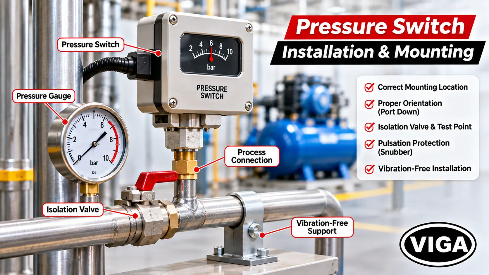
A pressure switch can only be as accurate as the pressure that reaches it. Most setpoint drift blamed on “a faulty switch” is really a mounting problem: heat, vibration, pulsation or a twisted housing.
- Choose the tapping point. Mount close to the point that matters, such as the air receiver rather than the compressor discharge. Keep the switch accessible at eye level so the setpoint can be checked later without a ladder.
- Check the ambient and media temperature. Compressor rooms in Delhi NCR regularly cross 40 °C in May and June, and a switch bolted beside an aftercooler or cylinder head sees far more. Compare both temperatures with the datasheet before choosing the spot.
- Respect the orientation. Most mechanical switches are designed for vertical mounting with the pressure port facing down. Some designs shift setpoint when mounted sideways, so follow the orientation stated by the manufacturer.
- Fit an isolation valve and a test point. A needle valve or gauge cock, plus a tee with a plugged test port, allows the switch to be isolated, vented and tested with a hand pump without shutting the line down.
- Add protection for the media. Reciprocating compressors and positive-displacement pumps produce pressure pulses that hammer the sensing element and make the contacts chatter, so a snubber or pulsation dampener belongs in that line. Steam service needs a syphon so condensate, not live steam, reaches the element.
- Match the thread before reaching for sealant. BSP and NPT threads of the same nominal size look alike but do not seal against each other. Tapered threads (NPT, BSPT) take PTFE tape or thread sealant; parallel BSPP threads seal on a bonded washer or O-ring, not on the thread.
- Tighten on the hex, never the housing. Hold the spanner on the pressure port flats. Turning the enclosure to tighten the joint can strain the sensing element and move the calibration before the switch has ever operated.
- Keep vibration off the switch. Do not hang a switch from a long nipple on a vibrating pipe. Bracket-mount it on a wall or frame and connect it with tubing.
- Plan the cable entry. Point the cable gland downward or form a drip loop, and match the enclosure IP rating to the location. Dust before the monsoon and condensation during it find their way into any entry that faces up.
Step 2 — Wiring the Electrical Contacts
A pressure switch is a control device. Its contacts are rated to switch a contactor coil, a relay or a PLC input; the motor current belongs on the contactor.
- Isolate and prove dead. Lock out the control supply, tag it, and confirm zero volts at the terminals with a tester before the cover comes off.
- Read the contact rating twice. Ratings differ for AC and DC, and for resistive and inductive loads. A contact that is comfortable at 230 V AC can be overloaded at 24 V DC or 110 V DC, because a DC arc has no zero-crossing to extinguish it.
- Match the contact material to the signal. A PLC input draws only a few milliamps, and standard silver contacts can build a surface film at that level, giving intermittent signals. Many manufacturers offer gold-plated contacts for low-energy circuits; specify them when ordering.
- Terminate properly. Use a gland sized to the cable’s outer diameter so the IP rating survives, crimp ferrules on stranded conductors, and connect the earth terminal on every metal enclosure.
- Land Common plus one contact. Wire C and either NO or NC, as decided below. Use the spare terminal for a separate indication circuit only if the rating allows it.
- Treat hazardous areas separately. A flameproof (Ex d) switch keeps its certification only when installed with certified glands and to the practices of IS/IEC 60079-14. Have the site’s hazardous-area competent person check it.
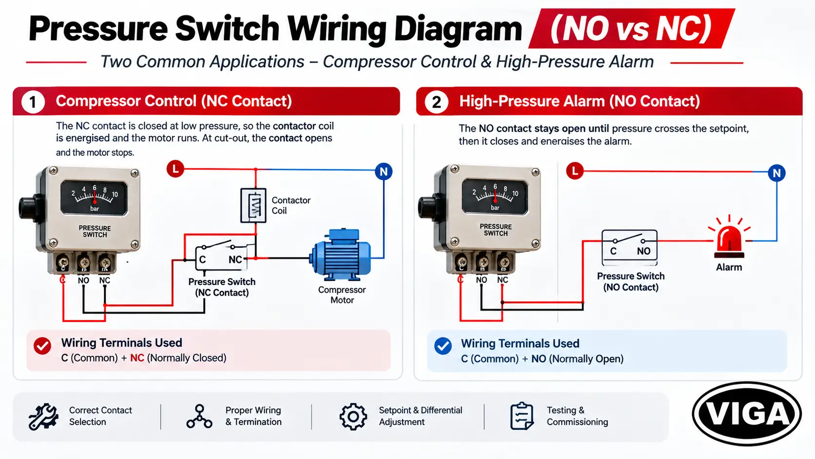
In the compressor circuit, the NC contact is closed at low pressure, so the contactor coil is energised and the motor runs; at cut-out the contact opens and the motor stops. In the alarm circuit, the NO contact stays open until pressure crosses the setpoint, then closes and energises the alarm.
NO vs NC for your application
Ask one question: what must happen when pressure rises through the setpoint? If a load must stop, wire C–NC. If something must start or an alarm must sound, wire C–NO. For a falling-pressure duty, reverse the logic, because the contact that closes as pressure drops below the reset point is C–NC.
| Application | What must happen | Contact to wire |
|---|---|---|
| Air compressor or booster pump control | Motor runs below cut-in, stops at cut-out | C–NC |
| High-pressure alarm | Alarm turns on above setpoint | C–NO |
| High-pressure safety trip | Run circuit breaks above setpoint | C–NC, in series with the run circuit |
| Low-pressure alarm | Alarm turns on below setpoint | C–NC |
| Lube oil or cooling water permissive | Machine may start only once pressure is proven | C–NO |
| Pump dry-run protection on suction | Pump stops when suction pressure is lost | C–NO, in series with the run circuit |
For protective duties, the direction of failure matters as much as the logic. Wire a trip so the healthy condition holds the circuit closed; a broken wire, loose terminal or failed switch then stops the machine instead of silently removing protection. An alarm wired through a NO contact has the opposite weakness, since a cut cable means it can never sound. Critical alarms are therefore often routed through a relay that stays energised while conditions are healthy.
Switzer pressure switch wiring
VIGA is an Authorized Distributor of Switzer, whose range on viga.in includes pressure switch models such as 021/023, 201/203/281, 204/208, PS 01, PS 601/602, PS 901/902/903 and S21, along with differential pressure switches. The C/NO/NC logic above applies across the range. Terminal identification, contact rating and the adjustment arrangement vary by model, so take them from the Switzer datasheet for the exact model being installed. VIGA’s technical team can share that datasheet and confirm the wiring before the switch reaches site.
Step 3 — Setting the Cut-In Setpoint
On a compressor or booster pump, two pressures define the job. The cut-in is the lower pressure at which the motor restarts; the cut-out is the upper pressure at which it stops. Switch makers often describe the same pair as the setpoint (where the contact changes over) and the reset point (where it changes back).
Before turning any screw, establish which point the main range adjustment actually moves. On many industrial switches the range screw sets the trip point on rising pressure and the reset falls below it by the differential. On many compressor-style switches, the scale is marked for cut-in and the differential adds on top. Mixing the two up makes every later adjustment appear to move the wrong pressure.
Choose a range that puts the setpoint in the middle. A common selection rule keeps the setpoint roughly between 25% and 75% of the switch range. A setpoint crowded against either end loses repeatability and leaves no adjustment margin.
Pressure switch setpoint adjustment, step by step:
- Close the isolation valve and vent the switch to atmosphere.
- Connect a hand pump or pressure source and a calibrated reference gauge at the test point. A test gauge of at least 0.5 accuracy class is a sensible reference for most plant switches.
- Put a continuity meter across C–NO, so the exact moment of switching is heard, not guessed.
- Set the scale pointer close to the target. Treat the printed scale as indicative only; the reference gauge decides the final value.
- Raise the pressure slowly, especially in the last 10% before the expected trip point. Note the reading when the meter changes state.
- Adjust the range screw in the direction marked on the switch, usually clockwise to increase, and repeat until the switch trips at the target.
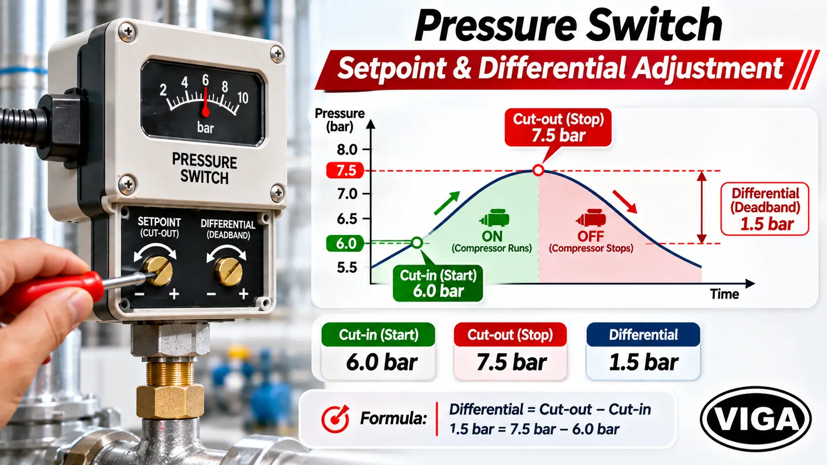
Worked example. A receiver must keep at least 6.0 bar at the tools and should never exceed 7.5 bar. That gives a cut-in of 6.0 bar and a cut-out of 7.5 bar. If the range screw sets the rising trip point, set 7.5 bar first, then use Step 4 to bring the reset down to 6.0 bar.
Avoid setting a switch by watching the plant gauge while the compressor is loading. Pressure climbs too fast to read the switching point, and the result is a setpoint that is off by however long the eye took to react.
Step 4 — Adjusting the Differential / Deadband
The differential, also called the deadband or hysteresis, is the gap between the pressure at which the switch operates and the pressure at which it resets. In the worked example above, the differential is 7.5 − 6.0 = 1.5 bar. This single number decides how often the motor starts.
Some switches have a fixed differential set by the mechanism; others carry a second screw that adjusts it. On many designs the differential also changes slightly across the range, so read the datasheet value at the actual setpoint rather than the headline figure.
What happens at each extreme:
- Too narrow: the motor starts and stops in quick succession, contacts wear, the starter heats up, and the motor may exceed the starts per hour its manufacturer allows. With a pulsating supply, a narrow band also makes the contacts chatter.
- Too wide: the system swings through a large pressure band. Tools or processes starve at the bottom, and the compressor spends energy pushing pressure higher than anyone needs at the top.
How to set the differential:
- Confirm the main setpoint from Step 3 is correct.
- Raise the pressure until the switch operates, then lower it slowly until the switch resets. Read the reset pressure on the reference gauge.
- Turn the differential screw to widen or narrow the band, following the direction marked on the switch.
- Recheck the main setpoint. On many switches the two adjustments interact, so moving the differential shifts the trip point slightly.
- Repeat steps 2 to 4 until both cut-in and cut-out land on target.
The right differential is not a number on its own. Cycle frequency depends on the differential, the receiver or tank volume, and the demand. A small receiver with a narrow differential will short-cycle no matter how well the switch is set, which is why a larger receiver is often the real fix.
| Symptom after commissioning | Likely cause | Adjustment |
|---|---|---|
| Motor starts every few seconds | Differential too narrow or receiver too small | Widen differential; review receiver size |
| Tools lose pressure before restart | Cut-in set too low | Raise the cut-in, keep the differential |
| Pressure overshoots the process need | Cut-out set too high | Lower the cut-out |
| Contacts chatter at the switching point | Pulsation reaching the element | Fit a snubber; check mounting |
Step 5 — Testing & Commissioning
Pressure switch commissioning proves three things: the switch operates at the right pressures, it does so repeatably, and the circuit it controls responds correctly. A switch that has only been set is not yet commissioned.
- Mechanical check. Confirm the process joint is tight, the switch is supported, the gland is sealed, the earth is connected and the cover gasket is seated.
- Dead-state continuity. With the switch depressurised and the circuit isolated, confirm C–NC reads closed and C–NO reads open.
- Insulation check. Test the control wiring insulation with the switch disconnected from any PLC card or electronics that the test voltage could damage.
- Repeatability test. Raise and lower the pressure slowly three times. Record the trip and reset pressure on each cycle. The three readings should agree within the repeatability stated on the datasheet.
- Loop test. Energise the control circuit, still with the motor isolated if possible, and confirm the contactor, alarm or PLC input changes state at the recorded pressures.
- Live run. Restore the motor supply and watch several real cycles under normal demand. Note the cycle time and check it against the starts per hour the motor allows.
- Leak check. On air service, apply soap solution to the process joints with the system at full pressure.
- Close out. Open the isolation valve fully, refit the cover, seal or lock the adjustment if the switch allows it, and tag the switch with its setpoint and differential.

The most common commissioning slip is the simplest one: the isolation valve left closed after testing. The switch then sees trapped test pressure and never operates again, and the first sign is a compressor that does not stop.
Commissioning record. Keep one line per switch so the next technician has a baseline to test against.
| Field | What to record |
|---|---|
| Tag and location | Equipment tag and where the switch is mounted |
| Make, model and range | As per nameplate |
| Contact wired | C–NO or C–NC, and what it controls |
| Required trip / reset | Design values from the process requirement |
| As-left trip / reset | Average of the three test cycles |
| Reference gauge | ID and calibration due date |
| Tested by and date | Name, signature, date |
Common Wiring Mistakes
Most of these are found during commissioning, which is the cheapest moment to find them. Any one of them can leave a compressor that will not stop, a pump that will not start, or an alarm that never sounds.
| Mistake | What happens | Fix |
|---|---|---|
| C–NO wired for compressor control | Motor never starts at low pressure, or runs only when pressure is already high | Move the wire to C–NC |
| Reading "normally" as the running state | Every contact choice is inverted | Base the choice on the depressurised state |
| Motor wired straight through the switch | Contacts weld or burn out | Switch the contactor coil, not the motor |
| AC-rated contact used on a DC circuit | Arcing and early contact failure | Check the DC rating, or switch through a relay |
| Silver contacts on a low-current PLC input | Intermittent or missing signals | Specify gold-plated contacts |
| Earth terminal left unconnected | Enclosure can become live under a fault | Earth every metal enclosure |
| Oversized or unsealed gland, entry facing up | Moisture and dust inside, terminal corrosion | Correct gland, entry downward, drip loop |
| Safety trip wired through a NO contact | A broken wire silently disables protection | Wire trips so the healthy state holds the circuit closed |
| No snubber on a pulsating line | Contacts chatter, setpoint drifts | Fit a snubber or pulsation dampener |
| Isolation valve left shut after testing | Switch never operates in service | Open and tag the valve during close-out |
Choosing the Right Switch Before Installation
Many installation problems are selection problems in disguise. A switch with the wrong range, a fixed differential where an adjustable one was needed, or an enclosure unsuited to the location cannot be fixed with a screwdriver on site.
Before ordering, have five answers ready: the media and its temperature, the working and maximum pressure, the trip and reset values required, the electrical load the contact must switch (voltage, current, AC or DC), and the area classification. With those, the choice narrows quickly.
VIGA is an Authorized Distributor of several pressure switch lines, which allows a like-for-like comparison rather than a single-brand recommendation:
- Switzer pressure and differential pressure switches for general industrial, compressor and process duties
- Indfos PSM and DPSM series, including heavy-duty and refrigeration models
- WIKA pressure switches, including the PSD 4 electronic pressure switch and the PSM 01
Plant teams across Okhla, Wazirpur, Mayapuri, Faridabad, Noida, Gurgaon and Baddi can reach VIGA’s technical team at 20 Chawri Bazar, Delhi, for help with model selection, datasheets and wiring confirmation before a switch goes on the line. Call +91-11-43025959 or +91-11-41582888, or send the application details through the contact page.
FAQ: Pressure Switch Installation
Q1. NO or NC for a pump?
For a booster or pressure-boosting pump, wire C–NC. The contact is closed at low pressure, so the pump runs, and it opens at cut-out to stop the pump. For dry-run protection on the suction side, wire C–NO in series with the run circuit, so the pump can run only while suction pressure is present.
Q2. How to set differential?
Set the main setpoint first against a reference gauge. Then raise the pressure until the switch operates, lower it slowly until it resets, and adjust the differential screw until the reset pressure is correct. Recheck the setpoint afterwards, because on many switches the two adjustments interact.
Q3. Why does it short-cycle?
Short-cycling usually comes from a differential set too narrow, a receiver or tank too small for the demand, pulsation reaching the sensing element, or an air leak that keeps dragging pressure down to cut-in. Widen the differential first and fit a snubber on pulsating lines. Persistent cases are covered in the pressure switch troubleshooting guide on viga.in.
Q4. Can a pressure switch start a motor directly?
Only a very small motor, and only if the load sits within the contact’s motor rating. In industrial installations, the switch operates a contactor coil and the contactor carries the motor current. This protects the switch contacts and keeps the motor’s overload protection in the circuit.
Q5. Which way should a pressure switch be mounted?
Most mechanical pressure switches are designed for vertical mounting with the pressure port facing down. Mount on a vibration-free support, away from hot surfaces, with an isolation valve and test point below the switch. The manufacturer’s datasheet states the permitted orientations for each model.
Q6. What is the difference between setpoint and differential?
The setpoint is the pressure at which the contact changes over. The differential is the gap between that point and the pressure at which the contact changes back. A switch set at 7.5 bar with a 1.5 bar differential trips at 7.5 bar and resets at 6.0 bar.