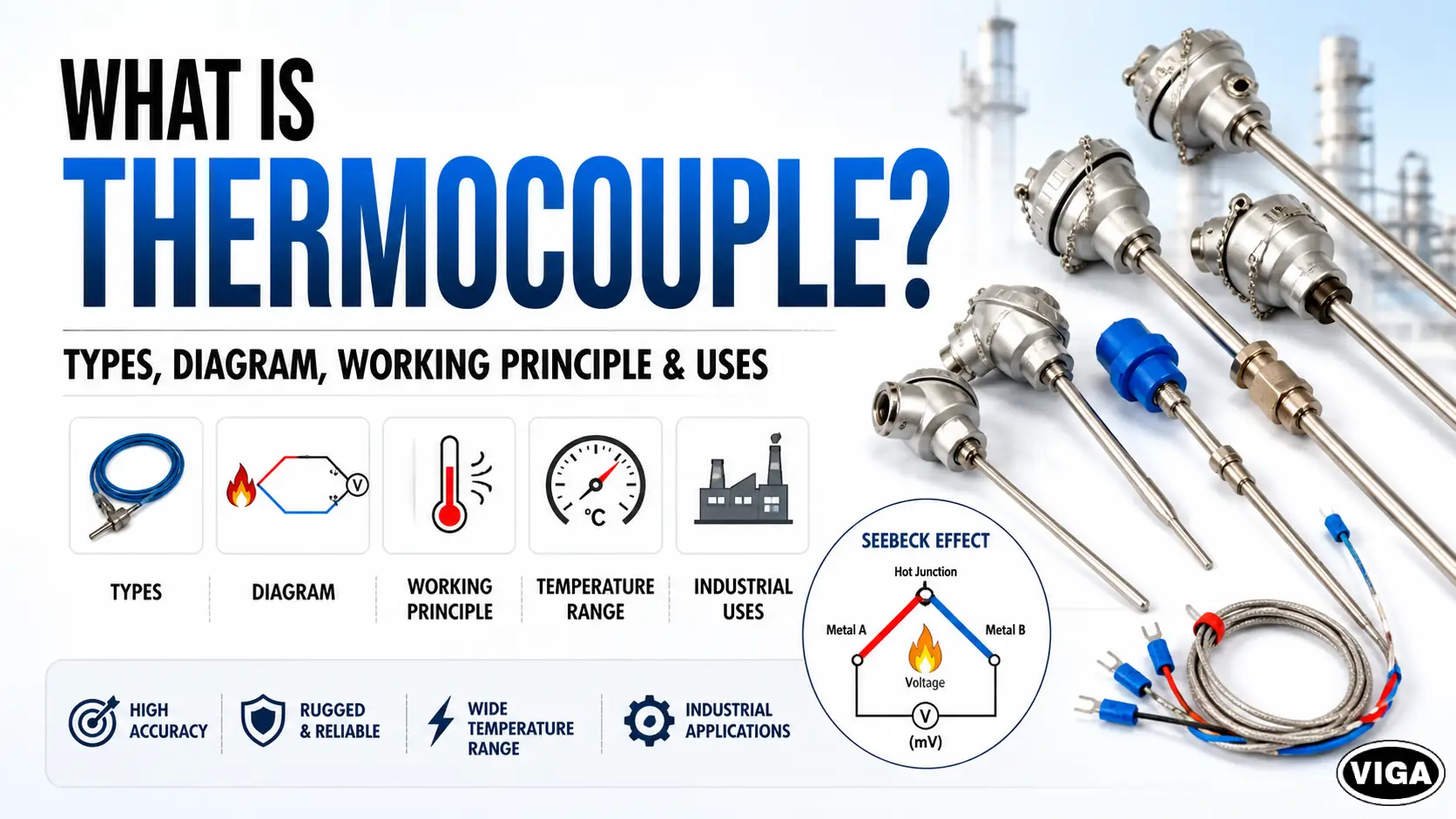
What is Thermocouple? Types, Diagram, Working Principle & Uses
Forget fragile glass thermometers. A thermocouple is an industrial temperature measurement sensor built to survive. It uses two different metal wires welded at a single tip. Heat that junction. It instantly spits out a tiny voltage signal—the Seebeck effect in action. Pure physics powering heavy industry.
Understanding the Industrial Thermocouple Sensor
Heat runs the show in heavy manufacturing. If your reactor runs too cold, the chemical batch dies. If a blast furnace gets too hot? Liquid steel eats right through the floor. You need hardware that refuses to fail under extreme pressure. Too hot, and steel melts through the furnace floor. You need a sensor that survives hellish conditions, costs pennies on the dollar, and delivers fast, reliable data to your control systems.
This is not a delicate laboratory instrument. It is a workhorse. It sits inside roaring incinerators, pressurized chemical vats, and freezing cryogenic chambers. Unlike standard thermometers that use expanding liquids, a thermocouple relies entirely on solid-state physics. Two different metals. One connection point. Heat it up, and it spits out a millivolt (mV) signal. The design is straightforward yet highly resilient, relying purely on solid-state physics to generate a millivolt (mV) signal when heated.
Plant managers and instrumentation engineers rely on the thermocouple temperature sensor because it works when everything else fails. It has no moving parts. It requires no external power source to generate its primary signal. It is completely self-powered by the thermal energy it measures.
If you are running a manufacturing plant, an oil refinery, or a commercial bakery, you are using these devices right now. But simply buying a sensor off the shelf is a recipe for disaster. You need to understand the physics, the metal combinations, and the exact failure modes.
The Physics Under the Hood: Thermocouple Working Principle
How does heating two pieces of metal create electricity? While it might seem counterintuitive, this process is governed by fundamental thermodynamics.
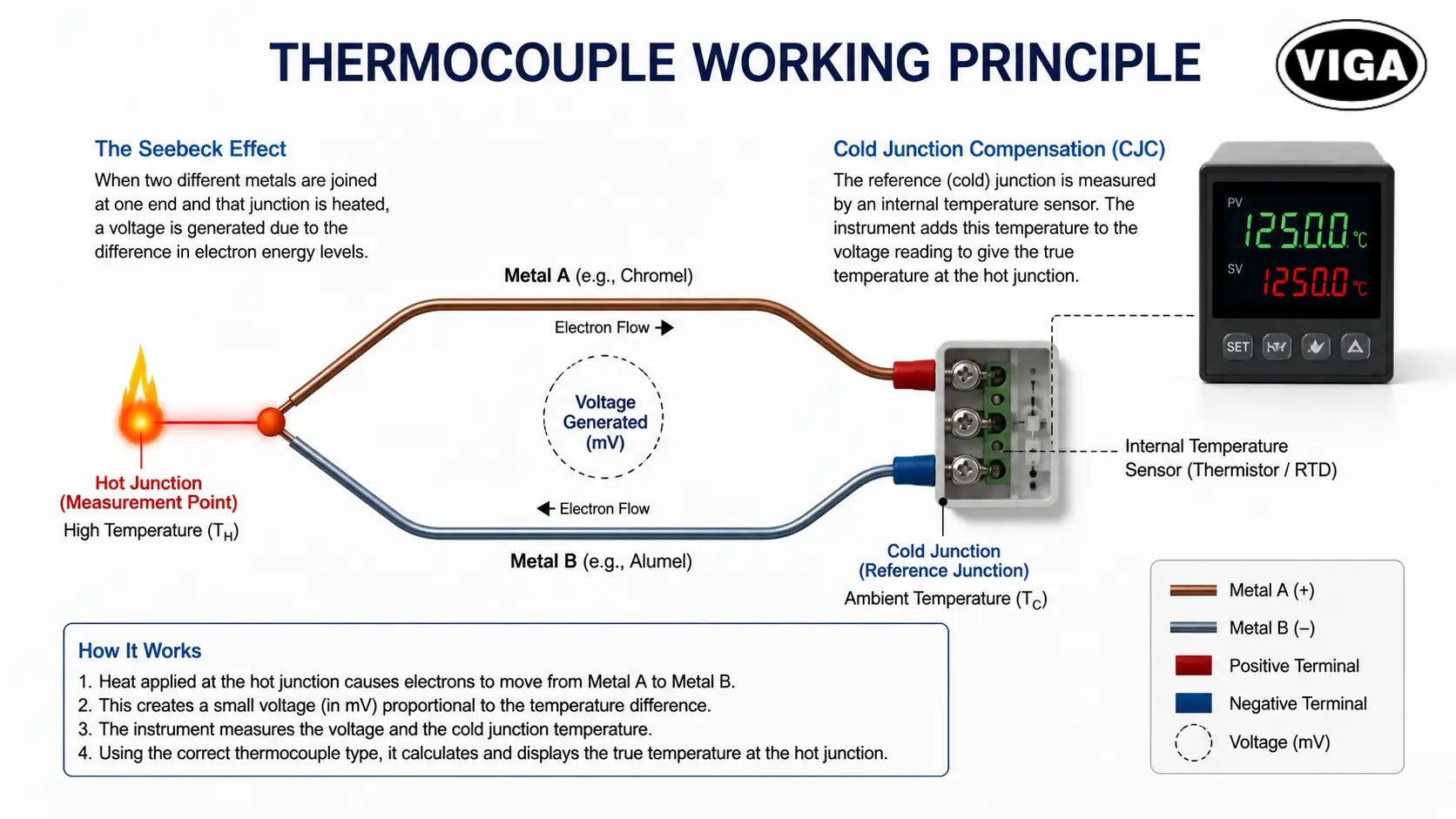
To understand the thermocouple working principle, we have to look at electrons. When you heat a metal, the electrons at the hot end gain kinetic energy. They start bouncing around rapidly. Because they are highly energized, they naturally diffuse toward the cooler, less energetic end of the wire. This creates a tiny electrical imbalance.
The Seebeck Effect: The Engine of Temperature Measurement
In 1821, a physicist named Thomas Johann Seebeck discovered something fascinating. If you take two different conductive metals (let’s say iron and copper), join them at one end, and apply heat to that junction, a continuous electrical current flows through the circuit.
Why two different metals?
This material difference is the core of the measurement.
Different metals have different atomic structures. Their electrons react differently to heat. If you used two wires made of the exact same copper alloy, the electron flow in both wires would cancel each other out. Net voltage: zero. But by using dissimilar metals—like Nickel-Chromium paired with Nickel-Alumel—the electrons in one wire move at a different rate than the other. This creates a measurable voltage potential at the open end of the circuit.
We measure this output in millivolts (mV). As the temperature rises, the millivolt signal increases. A PID controller or PLC reads this tiny voltage, runs it through a specific algorithm based on the metal types, and converts it into a readable temperature on your screen.
Cold Junction Compensation (CJC): The Hidden Hero
A thermocouple does not actually measure absolute temperature. It measures a temperature differential.
It measures the difference between the hot end (the measurement junction inside your furnace) and the cold end (the reference junction where the wires connect to your reading instrument). If the ambient temperature around your reading instrument changes, your entire temperature reading will be completely wrong.
How do we fix this? Cold Junction Compensation (CJC).
Modern thermocouple readers contain a secondary, highly sensitive internal thermometer (usually a thermistor or RTD) right at the connection terminals. This internal sensor measures the exact ambient temperature at the connection block. The microprocessor then mathematically adds this ambient temperature back into the equation.
The Big League: Thermocouple Types Chart and Temperature Ranges
Not all metals survive extreme heat. If you drop a copper wire into a glass-melting furnace, it vaporizes. This is why we have distinct thermocouple junction types categorized by letter designations. The letter dictates the exact metal alloys used.
Choosing the right type is the difference between an accurate reading and a catastrophic system failure.
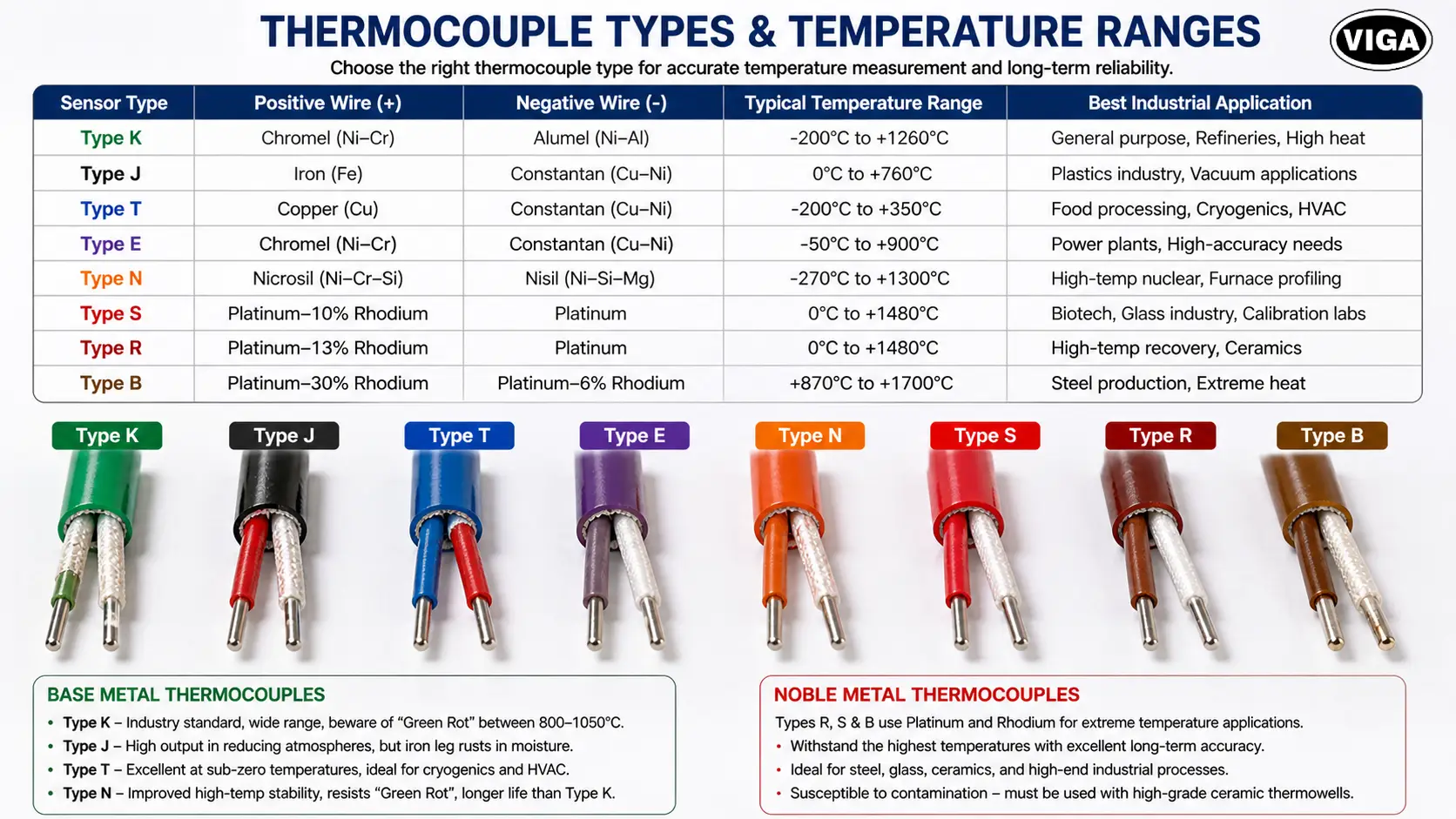
Thermocouple Types Comparison Table
| Sensor Type | Positive Wire (+) | Negative Wire (-) | Typical Temperature Range | Best Industrial Application |
| Type K | Chromel (Ni-Cr) | Alumel (Ni-Al) | -200°C to +1260°C | General purpose, Refineries, High heat |
| Type J | Iron (Fe) | Constantan (Cu-Ni) | 0°C to +760°C | Plastics industry, Vacuum applications |
| Type T | Copper (Cu) | Constantan (Cu-Ni) | -200°C to +350°C | Food processing, Cryogenics, HVAC |
| Type E | Chromel (Ni-Cr) | Constantan (Cu-Ni) | -50°C to +900°C | Power plants, High-accuracy needs |
| Type N | Nicrosil (Ni-Cr-Si) | Nisil (Ni-Si-Mg) | -270°C to +1300°C | High-temp nuclear, Furnace profiling |
| Type S | Platinum-10% Rhodium | Platinum | 0°C to +1480°C | Biotech, Glass industry, Calibration labs |
| Type R | Platinum-13% Rhodium | Platinum | 0°C to +1480°C | High-temp recovery, Ceramics |
| Type B | Platinum-30% Rhodium | Platinum-6% Rhodium | +870°C to +1700°C | Steel production, Extreme heat |
Deep Dive: Base Metal Thermocouples
Base metal thermocouples are the most widely deployed sensors in standard manufacturing, handling the vast majority of routine industrial tasks cost-effectively.
1. K Type Thermocouple: The Industry Standard
If you blindly pull a sensor out of a factory toolkit, it is probably a Type K. Made from Chromel and Alumel, it offers an incredible temperature range (-200°C to +1260°C). It resists oxidation at high temperatures beautifully.
Watch out for “Green Rot.” If you expose a Type K to a marginal oxygen environment (like a sealed furnace with small air leaks) between 800°C and 1050°C, the chromium in the positive wire selectively oxidizes. The wire turns green. Your millivolt signal drops aggressively. The sensor reads falsely low. This causes your PID controller to crank up the heat, potentially melting your furnace.
2. J Type Thermocouple: The Plastic Master
Type J uses an Iron positive leg and a Constantan negative leg. It generates a larger millivolt signal per degree than Type K, making it slightly more sensitive in its range. It thrives in reducing atmospheres (environments with no oxygen). You will find these buried inside plastic injection molding machines and extrusion dies.
The fatal flaw: Iron rusts. Never use a Type J in a humid or damp environment. Moisture will quickly corrode the iron leg, snapping the circuit.
3. T Type Thermocouple: The Deep Freeze Specialist
Copper and Constantan. Type T is highly stable at sub-zero temperatures. Because it uses pure copper, it offers excellent moisture resistance. You will see these strapped to liquid nitrogen tanks, cryogenic freezing units, and deep-freeze food transportation units. It caps out around 350°C because copper simply oxidizes too fast beyond that point.
4. Type N: The Upgraded Type K
Nicrosil and Nisil alloys. Type N was invented specifically to fix the “Green Rot” and high-temperature drift issues of Type K. It contains more chromium and added silicon. If you have an industrial thermocouple supplier offering Type N for your high-heat ovens, take the deal. It lasts significantly longer than Type K at sustained high temperatures.
Deep Dive: Noble Metal Thermocouples
For applications exceeding the melting points of standard alloys, noble metal thermocouples become essential. Noble metal thermocouples (Types R, S, and B) use Platinum and Rhodium.
While these sensors require a higher initial investment and are notably fragile, their ability to withstand extreme temperatures makes them indispensable for specific high-heat operations.
You do not use these for measuring boiler water. You use a thermocouple for furnace operations melting steel, forging glass, or operating high-end semiconductor manufacturing chambers. Because platinum does not oxidize, these sensors maintain incredible long-term accuracy. However, they are highly susceptible to contamination. If cheap metallic vapors touch the platinum at 1400°C, the platinum absorbs the vapors, ruining the calibration. They must always be protected inside high-grade ceramic thermowells.
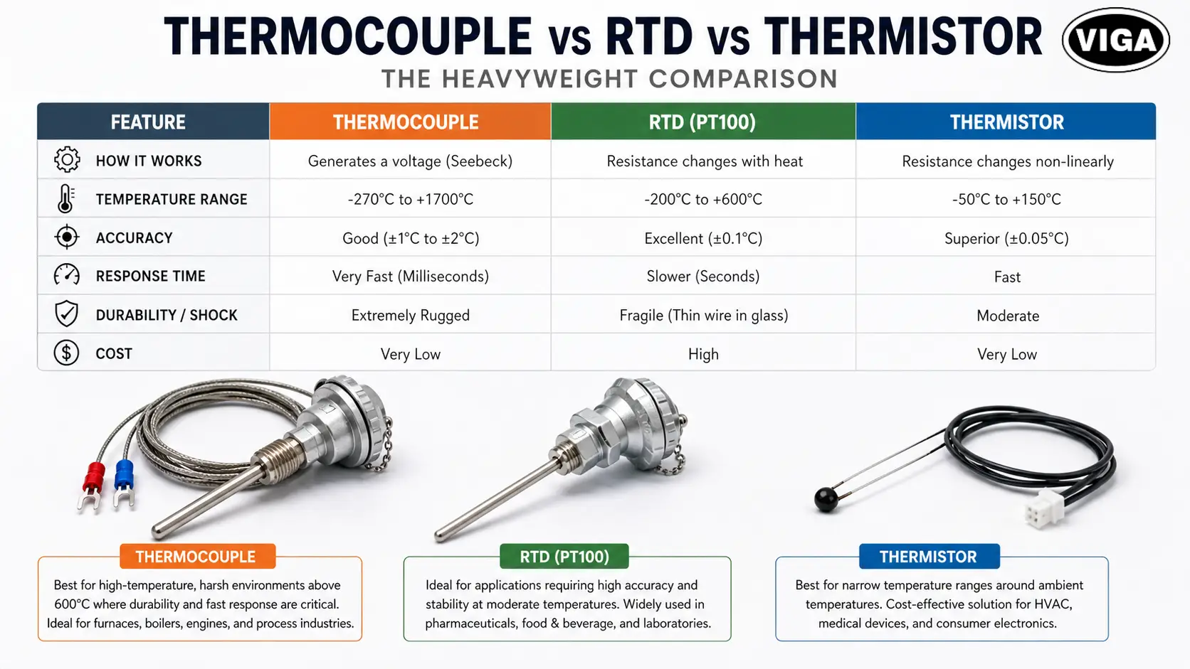
Thermocouple vs RTD vs Thermistor: The Heavyweight Comparison
A common mistake procurement managers make is typing “temperature sensor” into Google and buying whatever pops up first. You cannot just swap these technologies interchangeably. Let’s compare the thermocouple vs RTD (Resistance Temperature Detector) and Thermistors.
Feature | Thermocouple | RTD (PT100) | Thermistor |
How it Works | Generates a voltage (Seebeck) | Resistance changes with heat | Resistance changes non-linearly |
Temperature Range | -270°C to +1700°C | -200°C to +600°C | -50°C to +150°C |
Accuracy | Good (±1°C to ±2°C) | Excellent (±0.1°C) | Superior (±0.05°C) |
Response Time | Very Fast (Milliseconds) | Slower (Seconds) | Fast |
Durability / Shock | Extremely Rugged | Fragile (Thin wire in glass) | Moderate |
Cost | Very Low | High | Very Low |
Thermocouple Applications: Opt for a thermocouple when response speed and rugged durability are your top priorities, especially in environments exceeding 600°C. For instance, if a massive engine block vibrates violently, a thermocouple will simply shake with it and maintain the reading, whereas a fragile RTD would likely shatter.
RTD Applications: RTDs are the go-to choice for applications requiring pinpoint accuracy at moderate temperatures. Processes like pharmaceutical manufacturing or craft brewing demand the exact thermal data that an RTD provides.
Thermistor Applications: If your temperature window is narrow—typically around ambient or body temperatures—thermistors offer a highly cost-effective solution, though their functional range is heavily restricted.
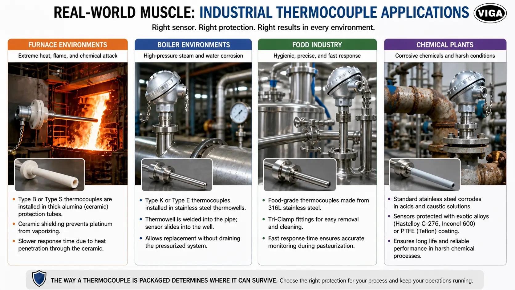
Real-World Muscle: Industrial Thermocouple Applications
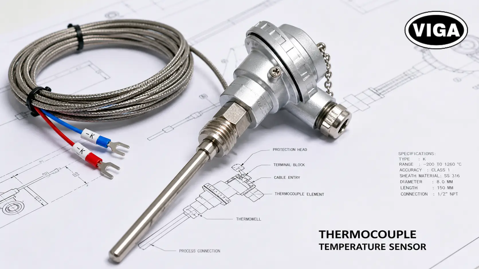
The way a sensor is packaged dictates where it can survive. The bare wire junction is almost never exposed directly to the process.
High-Heat Monsters: Thermocouple in Furnace and Boiler Environments
A thermocouple for a furnace must withstand aggressive chemical attacks, direct flame impingement, and thermal shock.
In steel mills and blast furnaces, Type B or Type S sensors are housed inside thick Alumina (ceramic) protection tubes. The response time is slow because the heat has to penetrate the ceramic first. But this shielding prevents the platinum from vaporizing.
For a thermocouple in boilers, the primary threat is high-pressure steam and water corrosion. Here, Type K or Type E sensors are installed inside heavy stainless steel “thermowells.” The thermowell is welded directly into the pipe. The sensor slides into the well. This allows maintenance engineers to remove and replace a dead sensor without draining down an entire 10,000-gallon pressurized system.
Precision and Hygiene: Food Industry and Chemical Plants
A thermocouple for the food industry operates under strict FDA and 3-A Sanitary Standards. Crevices breed bacteria. Therefore, food-grade sensors are encased in highly polished 316L stainless steel. They use Tri-Clamp fittings for instant removal and cleaning. Fast thermocouple response time is heavily prioritized here to catch sudden spikes during pasteurization processes.
In chemical plants handling sulfuric acid or caustic soda, standard stainless steel dissolves. Sensors must be encased in exotic alloys like Hastelloy C-276, Inconel 600, or coated in thick PTFE (Teflon).
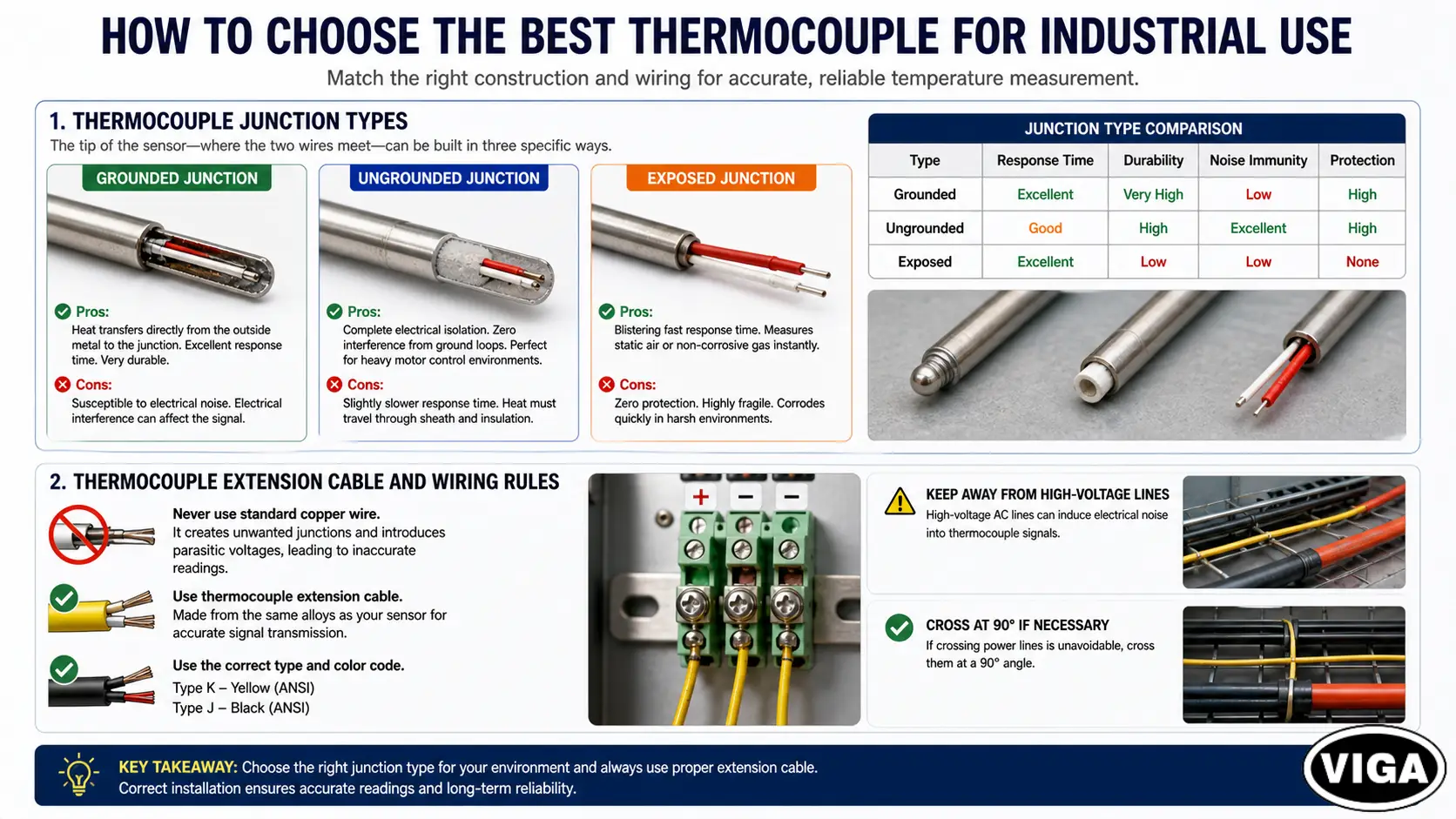
How to Choose the Best Thermocouple for Industrial Use
Selecting the right hardware goes far beyond picking a letter from the chart. You must match the physical construction to the process dynamics.
1. Thermocouple Junction Types
The tip of the sensor—where the two wires meet—can be built in three specific ways. This choice heavily impacts your thermocouple response time and electrical noise immunity.
- Grounded Junction: The thermocouple wires are physically welded to the tip of the outer metal protective sheath.
- Pros: Heat transfers directly from the outside metal to the junction. Excellent response time. Very durable.
- Cons: Susceptible to electrical noise. If your machinery has stray ground loops or massive electrical motors nearby, that electrical noise will travel up the metal sheath, hit the junction, and scramble your millivolt signal.
- Ungrounded Junction: The wires are welded together, but they are entirely surrounded by an insulating powder (Magnesium Oxide) inside the tip. They do not touch the outer metal sheath.
- Pros: Complete electrical isolation. Zero interference from ground loops. Perfect for heavy motor control environments.
- Cons: Slightly slower response time. The heat must travel through the sheath, then through the powder, before hitting the junction.
- Exposed Junction: The wires stick completely out of the sheath. Naked to the world.
- Pros: Blistering fast response time. Measures static air or non-corrosive gas instantly.
- Cons: Zero protection. Highly fragile. Corrodes immediately in harsh liquids or aggressive atmospheres.
2. Thermocouple Extension Cable and Wiring Rules
You cannot connect a thermocouple to a display panel using standard copper electrical wire.
If you use copper wire, you accidentally create new, unintended thermocouple junctions exactly where the copper meets your sensor wires. This introduces wild parasitic voltages into your loop. Your temperature reading will be garbage.
You must use specialized Thermocouple Extension Cable. This cable is manufactured from the exact same alloys as your sensor. Type K sensors require Type K extension wire (usually color-coded yellow in the US ANSI standard). Type J requires Type J wire (color-coded black).
Furthermore, run these signal wires far away from high-voltage AC power lines. A massive 480V motor cable will magnetically induce noise onto your tiny millivolt sensor wire. Cross AC lines at a 90-degree angle if you must, but never run them parallel in the same conduit.
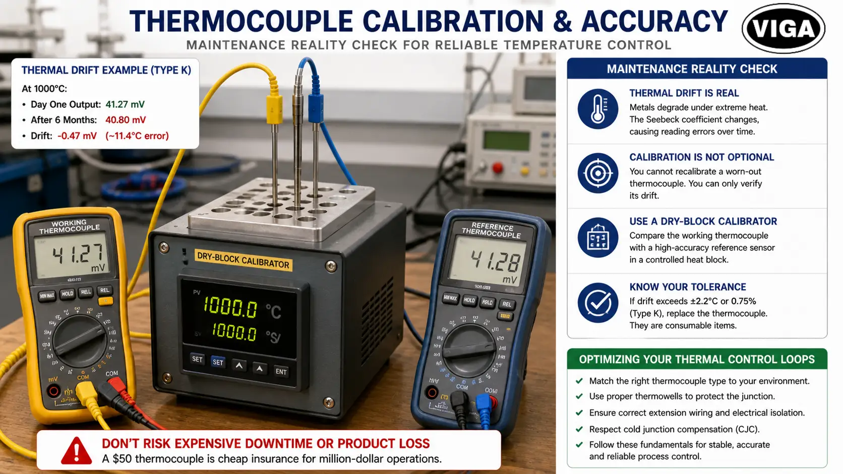
Maintenance Reality Check: Thermocouple Calibration and Accuracy
Metals degrade under extreme thermal stress. This degradation is called “Thermal Drift.”
Over months of operating at 1000°C, the atomic structure of the wire actually changes. Grain growth occurs within the metal. The alloys undergo microscopic phase changes. As the metal alters physically, its Seebeck coefficient shifts. A sensor that generated exactly 41.27 mV at 1000°C on day one might only generate 40.80 mV six months later. Your control panel will think the temperature has dropped, so it will add more fuel. You are now overheating your process without knowing it.
Thermocouple Calibration is not optional.
You cannot “recalibrate” a worn-out thermocouple. You can only verify its drift.
Industrial technicians use a dry-block calibrator. They insert the working sensor alongside a highly accurate laboratory-grade reference sensor into a controlled heat block. They compare the readings.
If your industrial thermocouple drifts beyond the acceptable tolerance (usually ±2.2°C or 0.75% for Type K), you throw it in the trash and buy a new one. These are consumable items. Do not risk a million-dollar batch of chemicals to save fifty dollars on a fresh sensor.
Optimizing Your Thermal Control Loops
Reliable industrial temperature control relies entirely on the integrity of your sensor data. A thermocouple acts as a solid-state voltage generator, driven by the Seebeck effect, and is heavily dependent on precise alloy pairings.
From preventing green rot in high-heat Type K arrays to isolating electrical noise with ungrounded junctions, every selection impacts your bottom line. Process stability relies entirely on the integrity of your sensor data. If your data is corrupted by bad extension wiring or thermal drift, your control algorithms will fail.
Stop treating these instruments as generic commodities. Match the metal to the environment. Protect the junction with the right thermowell. Respect the physics of the cold junction. Execute these fundamentals, and your thermal loops will remain tight, accurate, and completely under your control.
Frequently Asked Questions (FAQ)
Q1. How do I test a thermocouple with a multimeter?
A: To perform a basic field test, switch your digital multimeter to the DC Millivolts (mV) setting. Disconnect the sensor from the controller. Clamp your multimeter probes to the two thermocouple wires. Apply a heat source (like a heat gun) to the sensor tip. You should see the millivolt reading rise smoothly on the screen. If it stays at zero, or jumps erratically, the internal wire is broken and the sensor is dead.
Q2. Which is better for general industrial use, K Type or J Type Thermocouple?
A: Type K is generally superior for most industrial applications. It has a much wider temperature range and does not rust. Type J contains iron, which oxidizes rapidly in humid environments, leading to premature failure. Only select Type J if you are specifically working in a low-oxygen, reducing atmosphere where iron outlasts nickel-chromium.
Q3. What happens if I wire a thermocouple backward?
A: If you reverse the positive and negative leads at the controller terminals, your temperature reading will move in the opposite direction. As your process heats up, the temperature displayed on your screen will drop. Always follow the color codes. In the ANSI standard (US), the red wire is almost always the negative (-) lead.
Q4. How often should industrial thermocouples be calibrated or replaced?
A: There is no universal rule here. Context is everything. Pushing your process past 1000°C in a corrosive chemical bath? Thermal drift will eat that sensor alive. Expect to verify or swap it out every 30 to 90 days. Meanwhile, a low-stress commercial HVAC unit barely pushes the wire’s limits. You can easily get three to five years of dead-on accuracy there. Stop relying on factory estimates. Look at your actual heat load and mandate a strict, non-negotiable calibration calendar.
Q5. Can I cut or splice a thermocouple wire to make it longer?
A: You can cut it, but you should never splice it using standard wire nuts, solder, or standard copper wire. Splicing introduces new metals into the circuit, creating parasitic voltages that ruin accuracy. If you must extend it, use proper thermocouple extension wire of the same type, connected with specialized thermocouple-grade terminal blocks made from the matching metal alloys.