November 2025

FRL Unit
Blog

What an FRL Unit Does and Why Your Pneumatic System Needs It

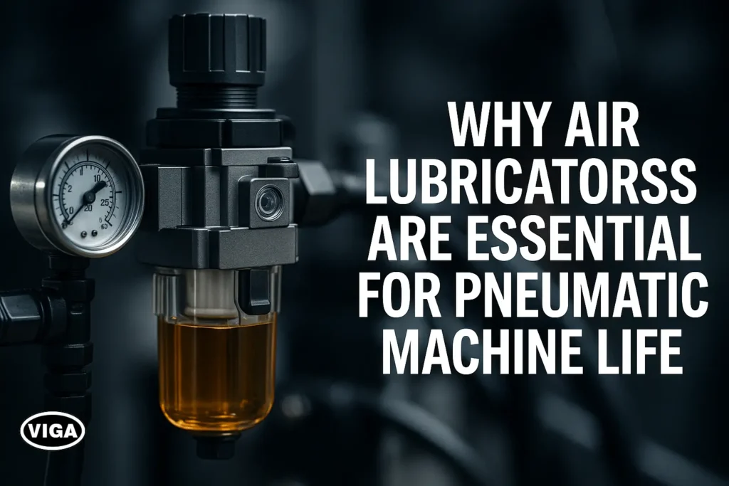
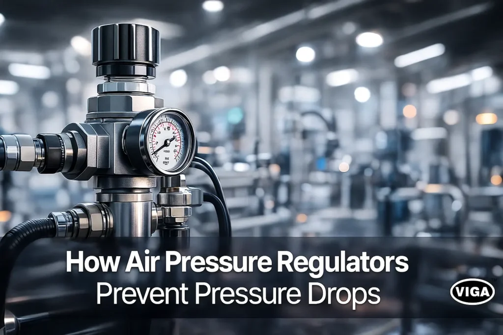
Your Pneumatic System Is Useless Without This — Know What an FRL Unit Does! Your pneumatic system can fail in seconds without an FRL unit. It may sound overly dramatic, but any seasoned maintenance engineer will confirm it’s a sobering fact. It’s like pouring low-grade, sandy fuel into a precision engine. You know the engine won’t last long, right? The same basic rule applies in industrial automation: quality power is necessary for system longevity. I’ve personally seen expensive machinery—a $50,000 piece of equipment—come to an immediate, dead stop. The cause wasn’t a PLC failure or a burnt-out motor. It was a simple, seized-up solenoid valve, crippled by condensation-induced rust because its air supply lacked proper preparation. The lost production time on that factory floor far exceeded the cost of a hundred FRL units combined. This is exactly why the FRL Unit (Filter, Regulator, Lubricator) is universally regarded as the critical component in air preparation. Without this essential trio, the very source of your factory’s power—compressed air—shifts from an energy medium to a damaging contaminant. What Exactly Is an FRL Unit? If you’re new to the topic and asking, “What is an FRL unit?” here is the most straightforward explanation you’ll find: FRL stands for Filter, Regulator, and Lubricator. It’s an integrated, three-part system installed in your compressed air line, positioned directly upstream of the machinery it serves. Its fundamental mission is three-fold: to scrub the air clean, to manage the pressure, and, often, to condition the air with a fine oil mist. Raw, untreated compressed air from a large industrial compressor is surprisingly harsh. It’s hot, full of condensed water vapor, microscopic grit, and minute particles of burnt compressor oil. If this “dirty air” hits delicate seals and internals, it’s highly corrosive and acts like a steady stream of liquid sandpaper. The complete Air Filter Regulator Lubricator combination cleans this corrosive medium, turning it into a stable, conditioned power source suitable for precision tools and sensitive industrial machinery. Why Every Pneumatic System Is Useless Without an FRL Unit You might look at the cost of an FRL and decide to “value engineer” it out of the setup. This choice is, unfortunately, a guarantee of catastrophic, non-preventable system failure. Importance of FRL Unit in Pneumatic Safety and Longevity: Moisture Damage: Condensation within a compressor’s storage tank creates massive amounts of water. Without the Filter, this water rushes downstream, stripping away the necessary factory grease inside tools and cylinders and causing instant rusting of critical metal components. Pressure Inconsistencies: The demand on a compressor constantly fluctuates. A tool designed for a steady 90 PSI can be suddenly blasted with 120 PSI or more from the line. The Regulator acts as a crucial barrier, preventing this kind of shock and seal blowout. Increased Tool Wear: High-speed air motors require constant, fresh lubrication. Without the Lubricator component supplying a fine mist, internal metal-on-metal friction increases exponentially, leading to bearing failure, component seizure, and premature burnout. Skyrocketing Maintenance Costs: Understanding how an FRL unit protects pneumatic equipment is simple math. A good unit costs anywhere from $50 to $200. An unpreventable production stoppage caused by a seized cylinder on your line can cost upwards of $5,000 per hour in lost revenue. From the point of view of safe, reliable engineering, running any piece of machinery off of raw air is negligent. The installation of an Industrial FRL Unit is a core component of preventative maintenance and a crucial insurance policy. Deep Dive: How Each Component Works To truly appreciate the FRL Unit Working Principle, you need to understand the physics governing the three distinct components. They work in tandem but perform separate, non-negotiable tasks. ✔ Filter (F) — The First Line of Defense Incoming air rushes into the filter bowl. Special vanes (deflector plates) force the air into a fast, downward spiral, creating a powerful cyclone (centrifugal force). This action flings heavier, larger contaminants (like water slugs and heavy dust) against the sides of the bowl where gravity allows them to drain. The now partially-clean air passes through a finely porous sintered element (typically 5 to 40 microns) to trap any remaining, fine dust particles. Primary Job: Aggressive debris and moisture removal in air lines. ✔ Regulator (R) — The Control Center Once cleaned, the air moves to the regulator section. Inside, a flexible diaphragm balances against a mechanical spring. You “set” the required pressure (e.g., 6 Bar) using the large knob. This control maintains a rock-steady output pressure. If the downstream pressure unexpectedly increases, a relief feature “bleeds off” the excess air to maintain your setpoint. Primary Job: Precise Air pressure regulation. This creates consistent torque, clamping force, and operating speed for your final equipment. ✔ Lubricator (L) — The Life Extender Finally, the conditioned air enters the lubricator bowl. It utilizes the fundamental Venturi effect: air accelerates quickly over a tiny opening, creating a localized vacuum. This negative pressure then sucks (or “draws”) specialized oil from the reservoir and instantly atomizes it into a fine, highly stable mist. This oil mist is carried to and deposits a necessary protective film on every valve, cylinder, and high-speed moving part. Primary Job: Critically reducing friction and preventing internal component corrosion. Benefits of Using an FRL Unit in Industrial Pneumatic Systems Investing in a high-quality Pneumatic FRL System delivers a powerful return on investment (ROI) that you can immediately observe on your shop floor. Extended Equipment Lifespan: Equipment that receives clean, consistently-pressurized, and lubricated air routinely lasts three to five times longer than those fed with raw air. Reduced Downtime: You drastically cut the risk of emergency failures. Fewer unplanned stops means your manufacturing processes keep moving predictably. Energy Efficiency: A regulated pressure saves energy. Why waste expensive compressed air feeding a line at 110 PSI when the tool you’re powering only needs 80 PSI? The regulator stops this waste. Enhanced Safety: Equipment pneumatic tools safety is based on predictable force. An FRL mitigates the significant risk of pressure spikes that can lead to catastrophic component failure, hose whipping, or a dangerous breakdown. Improved Air Quality: Protecting expensive downstream components (like proportional valves) from upstream particulate contamination. Signs Your Industry Needs an FRL Unit Right Now If you are seeing any of these

Air Lubricators
Blog

Why Air Lubricators Are Essential for Pneumatic Machine Life

The Secret to Longer Pneumatic Life — Why Air Lubricators Matter More Than You Think! Dry Air is a Destroyer When you are deeply involved in manufacturing or industrial maintenance, your most overlooked source of catastrophic failure is the very thing you use for power: dry compressed air. I can tell you from decades of experience, your Air Lubricator is the single best, simplest piece of defensive engineering you can install. It’s what protects your large investments from an incredibly simple flaw. Let’s face an unavoidable truth: dry air destroys pneumatics faster than anything else. You might have budgeted tens of thousands for high-end compressors and meticulously regulated valves, but once you start running air—filtered, moisture-stripped air—through any rapidly moving pneumatic part, you’ve created an environment of severe, accelerated self-destruction. The reason is a total absence of a separating layer. Think about a critical process stopping—it’s usually not a monumental failure; it’s a minor thing: A High value precision valve that, after three months, just can’t snap its internal spool to the correct position. That phenomenon, the dreaded sticking valve, is a textbook example of component destruction through zero pneumatic tool lubrication. What you are hearing and seeing is uncontrolled metal or plastic rubbing against metal under extreme, repetitive stress. Your focus should be on the small investment that delivers huge operational freedom. The lubricator isn’t an option; it’s an absolute necessity. It is the crucial guardian that ensures genuine tool life enhancement, converting an abrasive medium into a seamless vehicle for internal protection. Ignoring this basic truth leads directly to unpredictable and often catastrophic failure cycles.  What Is an Air Lubricator? Before you can appreciate the complex mechanical protection it provides, we must simplify its purpose. So, for someone completely new to this: A Pneumatic Air Lubricator is basically an on-demand, precise dispensing machine for lubricant that gets carried along inside your existing pipe network. It automatically transforms a specialized, low-viscosity oil into a cloud and injects it into the compressed air flow before it hits the point of work. The system function, or the core Air Lubricator Function, is this: ensuring that critical, dynamic parts that are otherwise impossible to manually grease receive an uninterrupted film of protection. That layer is the barrier that prevents the surfaces of your valves, spools, and cylinder rods from ever making contact with each other. You usually see it in the field as the final component in what’s called the FRL Lubricator Unit (Filter, Regulator, Lubricator). If the filter cleans the air and the regulator stabilizes the pressure, the lubricator handles the final and perhaps most important piece of conditioning: adding a controlled dose of mist lubrication. It has to be the last component because putting oil upstream would destroy filters and cause control problems in the regulator’s pressure mechanism. Its careful placement guarantees that every cubic foot of air leaves ready to work and ready to protect its equipment. Why Pneumatic Components Need Lubrication Any experienced maintenance technician knows the real enemy is friction, not just dust. To be a true expert in pneumatics is to grasp the engineering logic of why friction is a system killer and why lubrication is an immediate necessity. This goes to the heart of the Importance of air lubricators. Real-World Mechanics and the Path to Wear We rely on incredibly fast-moving components that depend entirely on close tolerances and intact seals. Without a proper lubricating film, these dynamics work to tear themselves apart. Friction-Induced Heat is a Seal Killer: Actuators run at high cycles per minute. In dry conditions, friction rapidly generates substantial heat right where the piston seals meet the cylinder wall. What happens next is irreversible: That heat hardens the polymer or rubber seals, turning them brittle and compromising their flexibility. Once the seal loses its supple nature, it starts cracking. Pneumatic Wear: Once a seal is brittle or compromised by high heat, its integrity is lost. This results in leakage and the abrasive scouring of the cylinder’s internal surface. The Pneumatic Wear then accelerates—microscopic scores and imperfections develop, allowing more friction, more heat, and more wear. The Stiction Nightmare: This is the most visible operational fail. When a valve’s internal spool requires more pressure (more energy) to begin sliding than to continue sliding, it “sticks.” This is usually due to microscopic dry air damage and an utterly depleted seal layer. This translates directly to an instant hit on production efficiency and system reliability. Essentially, when a lubricator is skipped, you trade preventative wear prevention for an immediate and guaranteed acceleration of your components’ age, resulting in an unjustifiable reduced lifespan across your system.  How Air Lubricators Work How does a single drop of oil, released under control, manage to travel 50 feet and perfectly coat an O-ring inside a manifold? It’s not magic; it’s an elegant use of air dynamics. The technology’s effectiveness lies in its core component, the sophisticated oil mist generator. The oil must be broken down to the sub-micron level so that it remains suspended in the high-speed air. The Sight-Feed Control: Oil is stored in the reservoir, but it’s released with meticulous precision. A needle valve or metering screw controls the lubricator oil flow, creating the slow, steady drip rate you observe in the sight-feed glass. This flow is constrained, ensuring you are not flooding the system but rationing the dose perfectly. The Venturi Principle (Generating Vacuum): The incoming compressed air passes through an internal restriction—the Venturi throat. By decreasing the volume for the air flow, you drastically increase the air velocity, which—due to basic physics—causes a rapid drop in local static pressure. That drop creates a crucial, local vacuum. Oil Uptake and Atomization: This generated vacuum then acts like a miniature, precise pump, drawing the precisely metered drop of oil up from the reservoir. When the single oil droplet meets the extremely high-velocity air in the restriction, it’s shattered into a fine aerosolized suspension—the perfect lubricating mist lubrication. Distribution: Air as the Carrier: Now, this is key. The minute size of the oil particles ensures they do not fall out of the airstream immediately (like rain). Instead, the high-pressure air acts as a perfect delivery vehicle, ensuring every complex, tiny channel, O-ring groove, and valve seat

Air Pressure Regulators
Blog

How Air Pressure Regulators Prevent Pressure Drops

The Air Regulator Difference: Achieving Rock-Solid Operational Stability Air Pressure Regulators are the most undervalued assets in the vast majority of industrial setups, yet they prevent production disasters every single minute of every working day. You know that gnawing anxiety—that tiny, cold fear that hits when a high-speed assembly sequence on your line hesitates, stutters, or momentarily loses power. We’ve all seen the resulting disaster: a part is misaligned, a torque wrench underperforms, or a paint finish suddenly appears patchy. The cause, far too often, is traced back not to a faulty machine, but to the inherently unpredictable nature of its energy source. Let’s be candid. You spend a fortune on a high-end air compressor, capable of delivering a beastly 175 PSI. Logically, the air should be perfect at the workhead, right? Wrong. The moment a compressor cycles, a distant machine engages, or a major line manifold is accessed, that output pressure violently shifts. Imagine running an automated screw feeder that requires precisely 75 PSI for repeatable performance. Without consistent control, an air spike might blow a seal, while a sudden pressure drop might cause an unacceptable half-turn on a crucial fastener. This true industrial scenario illustrates why we constantly fight the specter of instability, underscoring the massive importance of an air pressure regulator for continuous output quality. The truth is, reliable operation hinges entirely on controlling the very air you feed your machines. What Causes Pressure Drops in Pneumatic Systems? You cannot fix chaos until you know its root cause. If your machines are consistently battling chronic performance problems, a significant pressure drop in pneumatic systems is the likeliest culprit. You might be paying a premium for compressed air, but your machinery is receiving volatile fluctuations, contributing to significant Pneumatic Pressure Loss. We have to drill down into the non-negotiable answers to Causes of Pressure Drops : The Turbulent Compressor Source: I know you paid for a steady supply, but the fact is, the tank is always refilling, starting, and stopping. This natural fluctuation means the high-side supply line pressure constantly varies by 10 to 20 PSI—it’s never truly constant. Without an Air regulator for compressor output, that erratic feed immediately introduces chaotic pressure spikes and falls across your entire compressed air system. Simultaneous Demand Overload (Systemic Starvation): The common issue of multiple tools or actuators activating concurrently—an air blast here, a major clamp there. These demands instantly create a brief but substantial localized vacuum, starving the immediate local area of volume (CFM) and dramatically dropping the pressure. This peak flow deficiency is why many Why pressure drops happen in air lines incidents occur only during maximum production speed. Chronic and Undiscovered Line Leakage: This is the invisible money pit. You’d be surprised how much pressure—and, thus, money—is hemorrhaging through tiny, neglected seals or slightly loose hose clamps across a large facility. That persistent, collective hiss forces your compressor to run longer and harder, which directly and consistently degrades the baseline stable air pressure available to your devices. Air Quality and Pipeline Resistance: If you aren’t diligently maintaining your upstream dryer and filter, moisture and contaminants collect inside the piping. Over time, that buildup reduces the actual flow diameter, creating frictional resistance that mimics a chronic bottleneck. This hidden choke point translates into a measurable loss of performance right where the actuator requires its full push force. Design Flaws: The Curse of Undersizing: A mistake made years ago by a systems designer: installing piping that is simply too small for today’s demand load. While you can send enough pressure, the piping can’t pass the volume without creating significant friction, resulting in an inherent pressure-loss defect built into the structural DNA of your pneumatic system efficiency setup. What Is an Air Pressure Regulator? Let’s be incredibly clear about the function. The Air Pressure Regulator acts as a dedicated pressure-reducing and stabilizing mechanism. Its purpose is entirely focused: it converts the unpredictable, high input pressure from the supply source into the precise, much lower set-point of stable air pressure required by the tool. And crucially, it holds that output number static, almost without exception. The Crucial Last Step Positioning is key for success. The regulator isn’t installed next to the huge main tank. Instead, you’ll find it strategically located immediately before the end-use device, usually integrated with the final filtration—often less than five feet from the pneumatic cylinder it controls. This point-of-use proximity ensures highly localized downstream pressure control , meaning its mechanical action accounts for the last moments of turbulence in the line, securing pressure consistency exactly where performance is judged. Know the Difference: Regulator vs. Relief Valve An expert distinction must be made here, as relying on one to do the job of the other is a frequent industrial mistake that risks costly damage: The Air Pressure Regulator (The Governor): This device performs the active work of control and reduction. Its mandate is operational—it makes sure the output pressure never exceeds the set-point during normal use. The Safety Relief Valve (The Safety Fuse): This component is designed to remain completely passive until a catastrophic event occurs—it only activates to dump pressure overboard if the entire system unintentionally over-pressurizes far above the regulator’s cap. Its sole job is the final defense against extreme failure and overpressure damage from structural rupture. The regulator is a full-time operator; the relief valve is merely the ultimate, last-second safety back-up. How Air Regulators Keep Air Pressure Stable How exactly does this clever arrangement of components achieve such unerring stability? The mechanical truth of how air regulators work is based entirely on the principle of mechanical counter-balance. Every reliable regulator utilizes its core components—the adjustable spring, the sensitive diaphragm (or piston), and the shut-off valve—in a perpetual negotiation. The moment you adjust the knob, this internal process begins: Setting the Control Standard (Downward Force): By turning the adjustment knob, you physically load the main internal spring. The resultant tension creates a measurable, downward mechanical force on the system’s flexible diaphragm or sensing piston. This is your commanded stable air pressure target (e.g., 90 PSI). Measuring the Operational Reality (Upward Force): On the opposite side of the diaphragm, a separate sensing line continuously channels the regulated output air pressure (the downstream pressure). This air creates a corresponding upward pressure force against the diaphragm, directly opposing the force of the spring. The Sweet Spot

Scroll to Top