March 2026

Weather Proof Pressure Switch Explained Working Principle & Uses
Blog

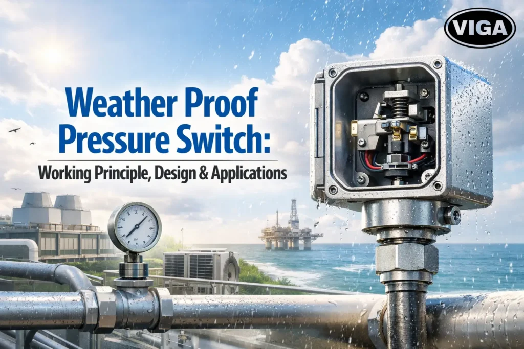
Weather Proof Pressure Switch Explained: Working Principle & Uses

A weather proof pressure switch is a device designed to operate reliably in outdoor environments by preventing moisture, dust, and environmental damage. It is widely used in water treatment, HVAC systems, and industrial outdoor applications. Field engineering demands reality. It demands hardware that doesn’t just work on a bench test, but holds up under driving rain, relentless coastal fog, and massive daily thermal shifts. When we discuss a weather proof pressure switch, we aren’t talking about “resisting a spill.” We are talking about critical process infrastructure that stands between a steady state of operation and a catastrophic system failure. If you are managing outdoor equipment, you know the cycle: condensation forms inside the housing, salt enters the thread-gaps, and suddenly, the switch becomes an expensive paperweight. This guide tears down the mechanics, the rating myths, and the installation errors that cause the majority of field-level instrumentation failures. Working Principle of Weather Proof Pressure Switch The weather proof pressure switch working principle is designed to resist environmental damage while maintaining accurate pressure control. The environment acts on every component of an outdoor pressure switch. You have to account for more than just rain. You have to consider internal heat cycles, high-velocity wind, and dust intrusion. The Problem with Air Exchanges The biggest hidden enemy in the field is a phenomenon often called “breathing.” During a hot day, air inside the switch housing expands. It leaks out past the cable gland. At night, when the temperature plummets, the unit cools down, the internal air contracts, and it sucks in fresh, moisture-laden air through that same path. If this keeps happening, eventually you have a pool of water resting on your electrical contacts. A properly engineered weather proof pressure switch stops this. It uses high-quality seals that withstand years of hardening and softening without losing their compression. Sensing Element Fatigue Diaphragm units offer high sensitivity. They are great for water-line pressure, but they do not love hydraulic shock. If you install one on a pipe that experiences “water hammer”—the banging you hear when a valve closes too fast—you are beating the life out of that diaphragm. Every pressure pulse is a micro-fracture event. If your system runs high-frequency pump cycles, pivot to a piston-actuated design. It trades a bit of raw sensitivity for immense physical resilience against shock loading. IP Rating and Protection Standards Outdoor pressure switches must be designed to handle moisture, dust, and temperature variations. Do not get hung up on the number alone. An IP rating pressure switch tells you the level of protection, but not the duration. IP65 (Dust tight, water jet): It survives a heavy spray. Do not mistake this for being “submersible” or “weatherproof” in a high-intensity marine setting. It belongs in a semi-sheltered area, like under a roof eave. IP66 (Dust tight, powerful water jets): This is the baseline for outdoor, unsheltered use. If it sits on an open pipe rack, IP66 is your entry fee to reliability. It deals with heavy rain without skipping a beat. IP67 (Dust tight, immersion): This protects against incidental contact with water. It implies that even if the ground-mounted vault where your switch sits floods to a foot deep, the electronics survive until the water drains. Expert Pro-Tip: Never rely solely on an IP rating if your cabling is trash. You can buy the most robust, marine-grade, IP67-rated switch on earth, but if you run the cable through a standard indoor plastic cord grip, you’ve introduced a direct path for water. Use armored glands or liquid-tight conduit fittings specifically rated for exterior utility environments. Industrial Applications of Weather Proof Pressure Switch An industrial weather proof pressure switch is commonly used in outdoor installations such as water treatment and HVAC systems. Strategic Applications in Industrial Work Water Treatment Infrastructure This is arguably the most brutal environment. You have moisture, heavy cleaning chemicals, and high-frequency start-stop cycles on lift station pumps. Here, an industrial weather proof switch needs two things: 316-grade stainless steel wetted parts to resist chemical pitting, and high-quality gold-plated electrical contacts to prevent oxide buildup. Regular brass or mild steel fittings will turn into powder within a few years of chemical-laden air exposure. HVAC Outdoor Arrays Outdoor chiller systems operate in a “hot-cold” extremes loop. When the sun beats down, the outer casing reaches intense temperatures, and when the refrigerant dumps in, the switch port drops. This thermal expansion stress pulls on the switch body. Rigid, heavy-duty mountings that don’t warp under these gradients are vital. Marine and Coastal Pump Controls In these zones, humidity is saturated with salt. Salt creates an incredibly conductive film that spans across terminals. If your switch doesn’t feature an internal gasket-protected secondary cavity—a compartment specifically to shield the wiring from the pressure chamber—you are setting yourself up for shorts. Weather Proof vs Flame Proof Pressure Switch Most people in the procurement department see “Weather Proof” and “Flame Proof” and think they are similar. They are not. Feature Weather Proof (IP Rated) Flame Proof (Explosion Proof) Main Objective Keep external moisture out Keep internal fire contained Enclosure Gasket-sealed (often NEMA 4) Tight-fit, thick metal/threaded Venting Often breathers or weep holes Strictly flame paths (quenching) Cost Basis Seal/gasket quality Machining precision/safety specs Choosing the wrong one creates two risks. A Flame Proof switch used outdoors, without proper draining, often collects its own condensation inside. A Weather Proof switch in an explosive area is a failure point that creates a disaster. Always align your device with the atmospheric risk profile of the specific plot of land where it’s being installed. Installation and Calibration Best Practices The Calibration Ritual Remove Load: Always use a bypass valve to disconnect the switch from the live pressure pipe before calibrating. Never trust the static pressure on a live line when trying to hit a precision set-point. External Adjustment: Choose switches with external set-point dials that are protected by O-ring sealed covers. This allows field techs to dial in the switch during commissioning without opening the enclosure and exposing sensitive electronics to rain or wind. Vibration Mitigation: If you mount the switch directly to a

Flame Proof Pressure Switch Working Principle, Design & Applications
Blog

Flame Proof Pressure Switch: Working Principle, Design & Applications

A flame proof pressure switch is a safety device designed for hazardous areas that can withstand and contain internal explosions without igniting the surrounding environment. It is widely used in oil & gas, chemical plants, and explosive industrial environments. When you are standing in a Category 1 environment, you aren’t thinking about “synergies” or “frameworks.” You’re thinking about the seal integrity of your flame proof pressure switch and whether or not that unit is going to hold up when the plant experiences a massive pressure spike during a routine throughput change. The gear we install in hazardous zones isn’t just about measurement; it’s about life safety and preventing a minor hardware malfunction from escalating into a catastrophic incident report that hits the board of directors. Flame Proof Pressure Switch Design and Working Principle Most people look at a pressure switch and see a diaphragm, a spring, and some wires. An instrumentation engineer sees a cage. A flameproof pressure switch isn’t built to be light, pretty, or small. It’s built to be heavy, aggressive, and nearly impenetrable. Why Enclosure Mass Matters There is a specific reason why you feel that massive cast-aluminum or stainless steel housing. It’s not just to stop dirt. In the event that a process media manages to bypass the internal seal—usually due to an O-ring degradation—it can leak into the electronics housing. If the air-fuel ratio inside that box reaches an ignition point, the switch will spark. When that spark hits the gas inside, the pressure will rise rapidly. The flame proof enclosure design relies on two specific mechanical principles: Mechanical Rigidity: The walls of the enclosure are calculated to withstand the “Reference Pressure”—the peak pressure of an internal explosion—without cracking, yielding, or permanently deforming. If the metal bends, the internal joints expand, and the explosion leaks out. The Flame Path: This is the clever bit. Any escaping gas is forced to travel through long, thin gaps between the enclosure lid and the base. By the time that white-hot plasma leaves the box, the mass of the metal housing has stolen the heat from the flame. The temperature of the escaping gas drops below the auto-ignition temperature of the outside environment. That is why those housings have such precise, machined threaded lids. Never touch them with a file. Expert Pro-Tip: I’ve seen guys paint over the housing of an explosion-proof switch. Don’t do it. If you paint the gaps or the threaded path, you mess with the tolerances needed to cool that gas. You are literally compromising the safety factor to make it look “tidy.” Hazardous Area Classification and Zone Standards A hazardous area pressure switch is required for Zone 1 and Zone 2 environments. You’ll hear about Zones until you’re tired of it. It’s the baseline for everything. If you are ordering a Hazardous Area Pressure Switch, you need to speak this language or your plant audit is going to be a bloodbath. Hazard Area Gas Frequency Protection Logic Zone 0 Continuous Only Intrinsic Safety (Ex i) is allowed. Ex d won’t pass here. Zone 1 Likely under normal use Flame proof (Ex d) is the go-to. Rigid and reliable. Zone 2 Not expected; rare/short Ex n or Ex e are usually enough, though many choose Ex d for peace of mind. A lot of the pressure in this niche comes from “overspecifying.” It is expensive to install Ex d everywhere, but it is infinitely more expensive to accidentally use an Ex n switch where a Zone 1 explosion rating is required. When in doubt, checking the Gas Group—the actual chemical—is more important than the Zone itself. Intrinsic Safety vs Flame Proof Protection There is a constant war in plant design: do we use Intrinsic Safety (IS) or Flame Proof (Ex d) gear? It’s not a debate about which is better; it’s a debate about the philosophy of failure. Flame Proof: We assume an explosion will happen. We design a container to deal with it. We handle it through mass, geometry, and bolt-torque. Intrinsic Safety: We assume an explosion is impossible because the electricity involved is so pathetic—low voltage, low current—that even a short circuit cannot generate enough heat to light a match. Why go for the flame proof unit? Because sometimes the switch needs to actuate high-draw electrical equipment directly. IS cannot drive a big solenoid valve. Ex d can. If your switch has to physically toggle power lines, the “containment” approach is the only road left. Pressure Switch Working Principle The flame proof pressure switch working principle is based on containing internal explosions safely within the enclosure. Mechanics are rarely perfect. A pressure switch working principle involves a tug-of-war between the fluid pressure and a spring. If you ever sit in on a failure analysis, 90% of the time, the diaphragm is fine, but the range spring has relaxed. The Setup of a Standard Piston/Diaphragm Unit Sensing Element: Usually a Diaphragm for low pressure, Piston for high hydraulic pressure. The Travel: As pressure rises, the diaphragm moves. It pushes against a calibrated range spring. The Tipping Point: The end of the spring is attached to a linkage. This linkage touches a micro-switch button. That “click” is your signal. If you are dealing with rapid, pulsating flows (common in piston pump outlets), that spring and that button will chatter thousands of times an hour. This leads to Contact Pitting. Your signal fails because the contact points literally fused together from micro-arcing. Expert Pro-Tip: If your process involves heavy pulsation, ask the manufacturer for “damped” switching or an integrated snubber. Without it, you are buying a consumable, not a piece of permanent infrastructure. Technical Specifications and Material Selection An explosion proof pressure switch is commonly used in oil and gas industries. Why is there a $1,500 difference between a plastic-housing pressure switch and a Flame Proof Pressure Switch? It’s not just the sticker on the box. The Stainless Steel Argument For any serious Flame Proof Pressure Switch for Chemical Plants, skip anything but 316 Stainless Steel. Aluminum looks nice when it’s new, but wait three years in a sulfur-heavy or maritime environment. It pits, the screws seize in their holes, and you’ll have to cut

Pressure Switch Working Principle, Types & Applications
Blog

Pressure Switch: Working Principle, Types & Applications

Pressure Switch Explained: Working Principle, Types & Industrial Applications What is a Pressure Switch? A pressure switch is a device that monitors fluid or gas pressure and automatically opens or closes an electrical contact when a preset pressure level is reached. It is widely used in industrial systems to control pumps, compressors, and safety circuits. A pressure switch is a simple, binary hero. It isn’t a complex computer. It is a robust mechanism that feels physical pressure and slams a switch into place when things go right—or wrong. When that fluid or gas hits your set threshold, the contacts trip. Your motor turns on. The compressor vents. The safety alarm blares. Stop treating instrumentation as a textbook concept. It is not. It is the gatekeeper of your plant floor. Pressure Switch Working Principle When you understand the pressure switch working principle, you stop worrying about machine uptime and start controlling it. If your process pressure wanders outside the red line, your output quality drops, and your maintenance bill skyrockets. You need that reliability. Let’s get into the mechanics of why these devices work, how they break, and why your choice of switch will define your system’s life expectancy. Why Precision Controls Fail (And What You Need to Know) We see the same patterns repeated in facility after facility. Engineers order the cheapest switch off the shelf. They install it. It runs for three months. It begins “chattering,” then the contacts weld together, and the system burns out a motor. Then they blame the motor. It wasn’t the motor. It was the lack of understanding of the industrial pressure switch duty cycle. You are not just buying a sensor. You are buying a logic-gate that reacts to real-world force. To stop these failures, you need to think about two things: hysteresis and fatigue. Types of Pressure Switch There are different pressure switch types used in industrial applications. When you browse options, the mechanical vs electronic pressure switch debate is always the first wall you hit. Forget the buzzwords. Here is the field reality: The Mechanical Reliability: These rely on a spring fighting a physical force. They are ugly. They are cheap. But they are brutally reliable in high-vibration, “set-it-and-forget-it” setups. They don’t need a clean power supply to work. If your plant goes dark, the physical spring still holds the setting. The Electronic Precision: You pay more. You need an instrument technician to calibrate them. But they don’t drift like mechanical units do when the spring loses its “temper.” They offer digital deadband adjustment, meaning you can dial in a two-PSI differential so precisely that you almost entirely eliminate the start-stop hunting that kills pump life. Expert Pro-Tip: Always verify the vibration rating on mechanical units. If your pump house shakes the whole structure, a cheap mechanical switch’s spring will dance, causing the contacts to bounce and arc internally. Over time, that arcing carbonizes the switch contacts until they fail completely. Use a dampened mounting bracket if you aren’t sure. Sensing Elements in Pressure Switch How does it really know what the pressure is? It comes down to translating energy. The pressure switch working principle boils down to the sensing element. Think of the sensing element as the nervous system. The Diaphragm Approach: A flexible metallic disk. Think of it like a drum skin. Fluid hits it, it flexes, that flex pushes a rod. The Piston Approach: This is a machined sliding seal. It’s heavy duty. Use these for hydraulic systems that have rapid, violent spikes—the kind of pressure surges that would rupture a standard diaphragm. The Bourdon Tube: An internal C-shaped tube. Think of the classic paper noisemaker at a birthday party—that coiled-up tube that straightens when you blow into it. It’s elegant, very stable, but if it hits a corrosive environment, it will fail from the inside out. Once that sensing element pushes, it needs to hit the microswitch. This is the part that does the actual work. Inside that box, you have silver or gold-plated contacts. You want them to “snap” open or closed, not glide slowly. If they glide, you get sparks. If you get sparks, you get pit-holes in your metal contacts. A quality industrial pressure switch has a rapid, audible click for a reason. Choosing the Right Pressure Switch for Fluid How to Select the Right Pressure Switch Not all switches handle every fluid. Putting a standard rubber-diaphragm unit on a fuel line? Bad news. Within a week, the fuel will eat the rubber, and you’ll be leaking product all over the floor. Matching the Media You need to talk to your supplier about wetted materials. That means any part of the switch that actually touches your process media. Media Ideal Sensing Element Ideal Seal/Gasket Material Water / Coolant Stainless Steel (316L) Viton or Buna-N Hydraulic Oil Piston / Steel Buna-N (Nitrile) Compressed Air Phosphor Bronze EPDM Corrosive Acids Tantalum or Hastelloy PTFE (Teflon) Pressure switch calibration isn’t an art—it’s math. You check your gauge, you see the deviation, you adjust the set-point screw. If your reading says 50 PSI, but your mechanical gauge says 55, you’ve got an error. Never guess. Always calibrate against a trusted standard, not just by looking at a beat-up analog gauge hanging on a wall that hasn’t been verified since 1998. Pressure Switch Calibration & Maintenance Mastering The Hysteresis (Deadband) I want to spend a moment on the deadband. This is where most engineers fail the test. Your pump is trying to fill a tank. The switch triggers at 20 PSI to start the pump. It triggers again at 40 PSI to shut the pump off. That 20 PSI difference is your deadband. If your deadband is too tight, your pump is going to experience “short-cycling.” The motor hits 40, stops, and three seconds later, because a valve leaked or a pipe pulled a bit of flow, it drops to 39 and tries to start again. Starting a three-phase motor is when it pulls the most current and builds the most heat. If your switch doesn’t provide enough deadband, your motor starter contactor will be a melted blob in no

Industrial Differential Pressure Switch Guide & Working
Blog

Industrial Differential Pressure Switch Guide & Working

Differential Pressure Switch: Working Principle, Types & Applications A differential pressure switch is a device that measures the difference between two pressure points and activates an electrical contact when a preset pressure difference is reached. It is widely used in HVAC systems, industrial processes, and filter monitoring applications. Differential Pressure Switch: Technical Manual for Industrial Deployment If you are currently wrestling with erratic equipment shutdowns or trying to prevent the catastrophic failure of an expensive pump, you are likely looking for a differential pressure switch. Most engineers make the mistake of buying the first catalog item they see that fits the pipe diameter. That’s a gamble. A bad switch choice results in either ghost alerts that haunt your control room or, worse, zero response during a true over-pressure emergency. To manage your systems effectively, you need to understand how the physical pressure differential triggers mechanical movement. This isn’t about marketing—it’s about hardware. Working Principle of Differential Pressure Switch When we talk about a differential pressure switch, we aren’t talking about the absolute pressure relative to the earth’s atmosphere. We are looking at a specific math problem: P1 minus P2 = Delta P. Inside the housing, the magic happens in a sealed chamber. Imagine two separate ports. Port High (P1) is your supply or inlet side. Port Low (P2) is the downstream or suction side. A flexible element sits between them. In low-pressure setups, that element is a diaphragm (think of a sturdy rubber drumhead). In high-pressure industrial lines, it’s a precision-ground piston or a metal bellows. As pressure mounts at P1, the force pushes against the resistance of an internal spring. Once that force outweighs the spring, it trips a switch mechanism—usually a microswitch. It’s an “all or nothing” logic. The PLC sees a circuit closure, and suddenly, you have an actionable status update. Why Logic Fails (And Why It Doesn’t) If your industrial differential pressure switch feels “sluggish,” you are likely facing friction. This is why we insist on quality. A cheap switch will have “sticktion” (static friction) where the piston doesn’t slide perfectly. You might set it to trigger at 5 PSI, but due to grime or poor tolerances, it doesn’t fire until 7 PSI. In high-risk chemical environments, that 2 PSI difference is the gap between a process safely stopping and a pipe burst. Key Factors for Selecting a Differential Pressure Switch Selecting a switch isn’t a task for an intern. You need to verify four things before you open a PO. The Media Compatibility Audit Do you know what your “wetted parts” are made of? If you put a copper-beryllium sensing element into a system that uses aggressive, sulfur-rich process media, that metal is going to pit and fail within weeks. For aggressive fluids, stainless steel (316L) is the floor, not the ceiling. For acidic environments, look for Hastelloy or Monel housings. Never guess; check the material compatibility charts in the vendor’s PDF manual. The Static Pressure Trap Here is a mistake that burns million-dollar budgets: confusing the setpoint range with the proof pressure. Setpoint Range: The actual window (say, 0–20 PSI) where you want the switch to click. Static (Line) Pressure: The massive, crushing force the entire casing must handle just by existing in the pipeline (often 300 to 3000 PSI).If you have a 10 PSI range switch, but you put it on a 1500 PSI hydraulic line, the casing won’t hold. The internal pressure differential is tiny, but the ambient line pressure is enormous. Ensure your DP pressure switch housing is rated for the system’s “Maximum Working Pressure.” The “Deadband” Debate Hysteresis, or the “deadband,” is the space between the on and off trigger points. If your switch has a fixed, non-adjustable deadband, and your system has pump pulsations, you are going to experience “chatter.”Chatter is the rapid-fire opening and closing of your relay contacts. It creates heat, sparks, and electrical interference. In a high-vibration environment, you must have an adjustable deadband so you can “tune out” the minor pulses that aren’t real process anomalies. HVAC and Filter Applications Let’s talk about the most common field application: differential pressure switch for air filters. Your building management system (BMS) lives and dies by air flow. As your MERV 13 or HEPA filters catch dust, they create back-pressure. If you don’t track this, you’re essentially suffocating your air handler unit (AHU). The fan tries to push through a clogged wall of dirt, drawing more amps and potentially tripping the breaker. A good HVAC differential pressure switch is set at a point representing the “end of life” for the filter. When the delta-p hits, say, 1.0 inch water column, the switch clicks, sends a dry contact signal to your building controller, and someone gets an email: “Filter C, Blocked.” This is maintenance gold. It moves you from “calendar-based maintenance” (changing perfectly good filters because it’s the 1st of the month) to “condition-based maintenance.” You only pull a ladder out when you actually need to change the media. Feature Low-Range Switch High-Range Switch Typical Range 0.1 to 10″ Water Column 10 to 500 PSI Common Use Airflow/Cleanroom Hydraulic/Lubrication Sensing Style Diaphragm Piston Sensitivity Extremely High Moderate/Rugged Installation Best Practices Don’t install a switch just anywhere. The location is just as important as the component quality. Mounting Plane Matters: Some low differential pressure switches use gravity to help return the internal mechanism to a neutral position. If your installation guide shows “Mounting: Vertical,” and you mount it at a 45-degree angle, you are introducing artificial drift. Gravity will influence the trigger point. Stick to the vertical. Impulse Line Length: The pipes connecting your switch to the main flow line are the most vulnerable parts of your entire circuit. Keep them short. The longer the impulse line, the more chance you have of fluid buildup, clogging, or liquid hammering. Vibration Damping: If the pipe is shaking, the switch should be somewhere else. Build a simple mounting rack nearby. Connect the switch to the process line with stainless steel flexible tubing. This disconnects the sensor from the physical vibration of the pump or compressor. Expert Pro-Tip: Use a “three-valve manifold” assembly when installing your switch on liquid

Scroll to Top