August 2026

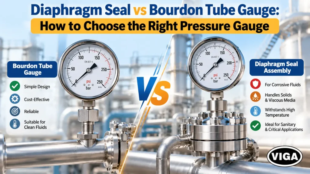
Diaphragm seal assembly vs Bourdon tube pressure gauge for industrial applications
Blog

Diaphragm Seal vs Bourdon Tube Gauge: How to Choose

Table of Contents [-] Diaphragm Seal vs Bourdon Tube Gauge: How to Choose the Right Pressure Gauge A Bourdon tube gauge does its job well for as long as the process fluid can sit inside a thin, dead-ended metal tube without attacking it, blocking it or solidifying in it. Once any of those things happens, the gauge either fails outright or, worse, keeps showing a believable number that no longer reflects line pressure. A diaphragm seal removes the fluid from the gauge entirely: a membrane takes the process pressure, and a sealed fill fluid carries it to the Bourdon tube. That protection costs money, adds some error and changes how the instrument is maintained, so it belongs only where the process genuinely demands it. The 3-Second Elimination Rule Pressure Gauge Selection Criteria Technical reference guide for gauge selection based on media and operational conditions Choose When Rule 1 Direct Bourdon gauge Fluid is a clean gas or liquid, carries no solids, stays freely flowing at the coldest temperature the line reaches, is compatible with the wetted material (copper alloy or 316L), and medium temperature sits inside the gauge datasheet limit (typically +60 °C for copper-alloy gauges, +200 °C for unfilled stainless gauges, +100 °C for liquid-filled stainless gauges) Rule 2 Diaphragm seal assembly Fluid attacks 316L or copper alloy at its real concentration and temperature; carries solids or fibres; thickens, cures or crystallises on cooling or standing; needs a cleanable, crevice-free sanitary connection (3-A or EHEDG where required); needs exotic wetted materials such as Hastelloy C276, tantalum or PTFE; or runs hotter than the gauge can take Rule 3 Neither: fix the real cause The problem is reciprocating-pump pulsation, mechanical vibration, steam, or overpressure spikes. Specify a snubber or restrictor, a liquid-filled case, a siphon, or a gauge saver. A diaphragm seal is not designed to cure any of these The temperature figures above come from WIKA’s published datasheets for its standard copper-alloy (model 111.10) and stainless steel (models 232.50 and 233.50) Bourdon gauges. Other manufacturers and models differ, so the datasheet of the gauge actually being installed governs. Decision Flowchart Pressure Instrumentation Selection Logic Failure diagnosis and diaphragm seal specification decision tree STEP 0 What is actually failing? Pulsation / vibration / steam / overpressure? YES Direct Action No seal needed. Snubber · liquid-fill · Siphon · gauge saver NO STEP 1: FLUID NATURE Clean, solids-free, flows freely when cold, compatible with 316L or copper alloy? YES STEP 2: TEMPERATURE Medium within gauge datasheet limit? ≤100 °C filled SS ≤200 °C unfilled SS ≤60 °C copper alloy YES DIRECT BOURDON GAUGE (steam: siphon) NO Proceed to STEP 3 ↓ NO DIAPHRAGM SEAL REQUIRED Corrosive · solids · viscous · crystallising · sanitary Proceeds to STEP 3 ↓ STEP 3: MOUNTING Medium ≤ ~100 °C and gauge readable at the nozzle → DIRECT-MOUNTED SEAL Medium > ~100 °C, vibration, or remote reading → SEAL WITH COOLING ELEMENT OR CAPILLARY For steam, a siphon usually brings a direct gauge back inside its limits before a seal is ever needed. The ~100 °C mounting threshold follows WIKA’s diaphragm seal selection guidance. Direct Bourdon vs Diaphragm Seal at a Glance Technical Comparison: Direct Bourdon vs. Diaphragm Seal Comprehensive evaluation of wetted parts, media compatibility, maintenance, and overall performance Factor Standard Direct Bourdon gauge Protected Bourdon gauge + diaphragm seal Wetted parts Bourdon tube, socket Diaphragm, lower housing Suited to Clean, compatible fluids Corrosive, plugging, viscous, crystallising, hygienic, hot Wetted material range Copper alloy, 316L, Monel Adds Hastelloy, tantalum, titanium, PTFE coatings and more Plugging resistance Poor with solids Good with flush or in-line designs Accuracy Gauge class only Gauge class plus seal effects Response Immediate Slower with long capillaries or cold, viscous fill Field swap Minutes, behind an isolation valve Assembly replaced or workshop-refilled Upfront cost Low Several times higher Where a Direct Bourdon Gauge Belongs The Bourdon tube is a curved tube of flattened, oval section, closed at its tip. Internal pressure pushes the oval towards round, the curve opens slightly, and a link, segment and pinion convert that small tip movement into pointer travel. EN 837-1 governs these gauges in Europe, covering nominal sizes from 40 to 250 mm and ranges up to 1,600 bar; ASME B40.100 is the corresponding US reference. On compressed air, clean water, hydraulic oil, lube oil and siphon-protected steam, nothing competes with it on cost, simplicity or reliability. Specifying a seal on these services buys nothing except extra error and a harder maintenance job. Temperature is where direct mounting runs out first. WIKA’s own datasheets make the limits concrete: Operating Temperature Limits Maximum medium and ambient temperature ratings by gauge construction Gauge construction (WIKA example) Max. medium temperature Ambient Copper-alloy wetted parts, model 111.10 +60 °C −40 to +60 °C Stainless steel, unfilled, model 232.50 +200 °C −40 to +60 °C Stainless steel, glycerine-filled, model 233.50 +100 °C −20 to +60 °C Two points often get confused here. The +60 °C figure attached to glycerine-filled gauges is the ambient limit; the medium limit for the filled stainless model is +100 °C. And every Bourdon gauge carries its own temperature effect: WIKA specifies up to ±0.4 % of span for every 10 K away from the +20 °C reference, before any seal is added. For steam, a siphon forms a condensate barrier so the gauge sees water at close to ambient temperature rather than live steam. For hot liquids and vapours above roughly 100 °C that a siphon cannot handle, WIKA’s diaphragm seal guidance calls for a cooling element or capillary. The weak point, though, is not temperature. It is geometry. The Bourdon tube is dead-ended. Fluid goes in and stays there, undisturbed, through every shutdown, every cool-down and every change of batch. Every failure described below grows out of that stagnant pocket. Media That Justify a Diaphragm Seal Corrosive media A corrosive fluid does not automatically mean a seal. If 316L or Monel wetted parts are proven compatible at the actual concentration and temperature, a
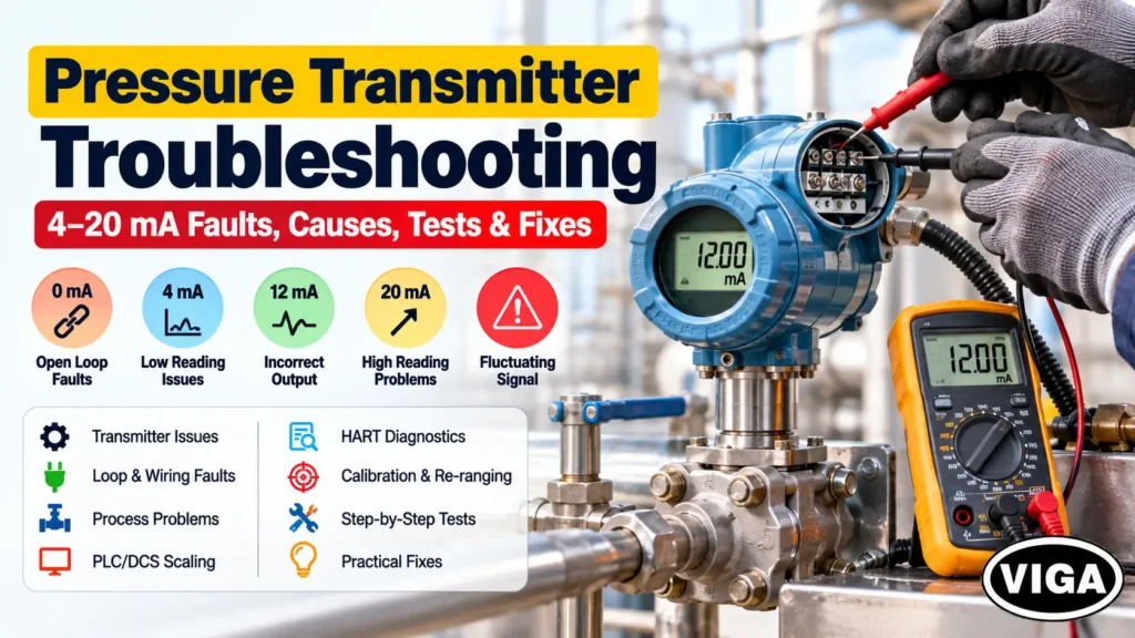
Pressure transmitter troubleshooting for 4–20 mA faults and diagnostics
Blog

Pressure Transmitter Troubleshooting: 4–20 mA Faults & Fixes

Pressure Switch Not Tripping? Causes, Tests & Fixes Table of Contents [-] A pressure transmitter showing the wrong 4–20 mA output is usually reporting a fault somewhere in the loop, the process connection, or the receiver configuration — not confessing that its own sensor has died. Measure the loop current first. The value on the meter already narrows down which of four domains the fault lives in, and that single measurement prevents most unnecessary replacements. The reliable order of work runs from the power supply and loop outward toward the sensor, with the transmitter itself treated as the last suspect, not the first. Quick Diagnostic Table: What the Reading Can Tell You The middle column matters as much as the first. A reading rules some causes in, but rarely proves any single one on its own. Observed current What it can indicate What it does NOT prove Check first 0 mA Open loop, lost supply, blown fuse, tripped IS barrier, broken wire, failed AI channel A dead transmitter Continuity, supply, fuse, barrier, AI channel ~3.6 mA (or device fault level) Configured downscale failure signal, or a genuine low reading near LRV Sensor failure — direction is set by config Device diagnostics; impulse line; range ~4 mA, process live Process at/below LRV, blocked/isolated tapping, URV set too high Sensor failure Manifold/root valve; LRV/URV vs duty ~8 mA (0–10 bar) ~25% of span (≈2.5 bar) Anything faulty Compare to a reference pressure ~12 mA (0–10 bar) ~50% of span (≈5 bar) A correct displayed value at the receiver Reference pressure; then PLC/DCS scaling ~16 mA (0–10 bar) ~75% of span (≈7.5 bar) Anything faulty Compare to a reference pressure ~20 mA, process normal Process at URV, URV set too low, trapped/blocked high pressure An over-pressure event Reference pressure; range; blocked line >20.5 mA Over-range/saturation, or a fault region A short circuit Reference pressure; diagnostics ~21–22 mA Configured upscale failure signal, or wiring/insulation fault A short circuit automatically Diagnostics; insulation/resistance test Fluctuating / noisy Process pulsation, ground loop, shield issue, VFD/EMI A failing sensor Grounding scheme; cable routing; damping Important — device-specific behaviour. Alarm current, saturation limits, minimum terminal voltage, loop-resistance requirements, diagnostic behaviour and trim procedures all vary by transmitter model. Treat the values in this article as a general framework and use the installed device’s datasheet and manual as the controlling technical reference. The Four Fault Domains Almost every wrong-output problem belongs to one of four domains. Isolating the domain before choosing a test is the core of efficient troubleshooting. Transmitter — sensor failure, electronics failure, a diagnostics alarm, sensor/zero drift, diaphragm damage, or an output-stage fault. Loop — power supply, fuse, IS barrier, wiring, cable resistance, excessive load, insufficient terminal voltage, grounding, or EMI. Process — closed root valve, wrong manifold sequence, blocked or frozen impulse line, trapped pressure, wet-leg or seal/capillary problems, or a genuine over-pressure. Receiver (PLC/DCS) — incorrect analog-input scaling, wrong LRV/URV entered at the receiver, wrong engineering unit, wrong channel mapping, or a signal-conditioning error. The current reading points toward a domain; the tests within each section below confirm the component. Safety Before You Test Loop diagnostics involve live electrical circuits and pressurised process connections. A series milliamp measurement must be made following the correct procedure for breaking into the loop; resistance or continuity functions must not be applied across an energised circuit. In hazardous areas, use the appropriate isolation and permit procedures, do not bypass intrinsic-safety barriers, and use only approved test equipment. Manifold and impulse-line work on a live or high-pressure system follows site isolation procedure. Site electrical/instrumentation procedures and the equipment manuals always take precedence over any general guidance here. Pressure Transmitter Troubleshooting Decision Tree 1 START Measure loop current in series (mA) 0 mA? → LOOP domain: supply, fuse, IS barrier, wiring, terminals, AI channel, continuity. Inject a known mA at the field end to test wiring + input card independently. Configured fault region (<=~3.6 mA or >=~21 mA, device-dependent)? → TRANSMITTER domain: read diagnostics, confirm fail-safe direction and alarm limits. Rule out blocked line / wrong range. Roughly 4 mA? → PROCESS + config: actual pressure, root valve, manifold, impulse line, LRV/URV. Valid 4-20 mA but DISPLAYED pressure wrong? → RECEIVER domain: verify current vs reference, then check PLC/DCS scaling, LRV/URV, unit, channel. Roughly 20 mA? → PROCESS + config: actual pressure, URV, trapped/blocked line. >20 mA? → Distinguish saturation vs configured alarm vs electrical fault (device documentation). Fluctuating? → LOOP/PROCESS: pulsation, grounding, shield, VFD/EMI, cable routing, receiver, damping. Slow / drifting? → PROCESS/TRANSMITTER: calibration, impulse line, diaphragm, seal, capillary, temperature. 2 Bench-test the transmitter only after field causes are eliminated. 3 Reconfigure / recalibrate / repair / replace according to the evidence. What a 4–20 mA Signal Actually Tells You A 4–20 mA transmitter represents pressure as a current. Two points are fixed by the range: 4 mA is the Lower Range Value (LRV, 0%) and 20 mA is the Upper Range Value (URV, 100%). The relationship is linear, which makes the expected output calculable and any error measurable. Forward (pressure to current): mA = 4 + 16 × (P − LRV) ÷ (URV − LRV) Current inside roughly 3.8–20.5 mA is treated as measurement information. Current below or above that window is generally either saturation (the process pushed slightly past range) or a device signalling a fault. The essential mental model: the current value narrows the fault domain; it does not, by itself, identify the failed component. A clean 4 mA can be a correct reading at LRV or a blocked tapping. A clean 20 mA can be a correct reading at URV or a trapped pressure. Only pairing the reading with a reference pressure and the device diagnostics turns a value into a diagnosis. The NE 43 qualification The NAMUR NE 43 recommendation gives the process industry a common framework for failure signalling on a 4–20 mA loop. In broad terms it reserves roughly 3.8–20.5 mA for valid measurement and treats current at or below about 3.6

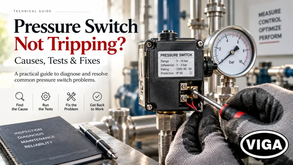
Pressure switch not tripping – causes, tests and fixes
Blog

Pressure Switch Not Tripping? Causes, Tests & Fixes

Pressure Switch Not Tripping? Causes, Tests & Fixes Table of Contents [-] A pressure switch that will not trip is not automatically faulty. Before assuming the switch itself has failed, confirm that pressure is actually reaching it, that the setpoint and differential are correctly set, and that the sensing path between the process and the switch is open. A switch that receives correct pressure but still does not change state points to the sensing element, the setpoint, or the switching mechanism. A switch that clicks but the connected equipment does not respond points to the wiring or control circuit instead. Working through that distinction, before replacing anything, resolves most pressure switch problems without a new unit changing hands. Before Replacing the Pressure Switch, Check These 3 Things Is pressure actually reaching the switch? Confirm the compressor, pump, or process is generating pressure, and that a gauge at or near the switch itself shows it, not a gauge reading taken somewhere else on the system. Is the path between the process and the switch fully open? A valve that is mostly open, a restricted sensing line, or a partly clogged sensing port can all hold a switch below its setpoint even while the rest of the system reads full pressure. Does the pressure at the switch actually reach the setpoint value? If the gauge at the switch reads below the setpoint, the switch is behaving correctly. There is simply nothing to trip on yet. If all three check out and the switch still behaves incorrectly, the fault sits inside the switch, and the decision tree below narrows it down. Safety First Isolate electrical power to the switch and the circuit it controls before opening a terminal cover or working on wiring. Confirm zero energy with a meter; do not rely on assumption. Isolate and safely depressurize the process line before removing a switch from service. Vent pressure through a proper point, not by loosening a fitting under load. Follow the site’s lockout-tagout procedure where one applies, including for work that looks like a two-minute job. Use the PPE the application calls for: safety glasses as a baseline, with hearing and face protection added where compressed air or steam is involved. A pressure switch that forms part of a safety shutdown or interlock should not be bypassed, jumpered, or overridden to keep a process running, unless the site’s own documented procedure explicitly permits it and specifies who is authorised to do so. Treat that as a plant safety decision, not a maintenance shortcut. Any live electrical testing described in this guide, including continuity checks and terminal inspection, is work for an appropriately qualified person following the site’s electrical safety procedure. This article explains what the tests reveal, not how to perform live electrical work without that qualification. Steam, high-pressure, toxic, corrosive, flammable, and hazardous-area service all call for more caution than a general guide can cover. In India, flameproof electrical equipment used in hazardous locations, including pressure switches on flammable gas, LPG, or hydrocarbon duty, falls under PESO (Petroleum and Explosives Safety Organisation, formerly the Chief Controller of Explosives) approval requirements under the Petroleum Rules. A certified flameproof switch should not be opened, modified, or swapped for a non-certified equivalent unless the manufacturer’s own certification or service procedure explicitly permits it; doing so otherwise takes the installation out of its approved condition. Where anything here conflicts with the specific manufacturer’s instructions or the site’s own procedure, the manufacturer’s documentation and site procedure take precedence over this guide. Troubleshooting Decision Tree Troubleshooting Decision Tree Pressure switch not tripping or not behaving correctly 1 Does pressure actually reach the switch? Check the gauge at the switch, the isolation valve, and the sensing line. No Not yet a switch problem. Troubleshoot the compressor, pump, process, isolation valve, or sensing line first. Yes Pressure is verified. Proceed to Step 2. 2 Does the switch actuate (click) at or near the expected setpoint? No Inspect the sensing port, the setpoint and differential settings, and the diaphragm, bellows or mechanism. Yes Mechanical actuation confirmed. Proceed to Step 3. 3 Does the controlled equipment (compressor, pump, alarm, contactor) respond when the switch actuates? No Inspect COM/NO/NC wiring, the relay or contactor, and the downstream control circuit. Yes Switch and wiring are functioning correctly. If cycling still looks wrong, re-examine differential, pulsation, or system sizing. A reading can be wrong while the gauge is entirely healthy. That is the point most troubleshooting misses. The diagnostic sequence Seven steps, in order. Stopping early is normal; most faults resolve by step five. Record what the gauge shows and what the plant expects, before anything is touched. A remembered value is not evidence. Ask what changed. A gauge that has read consistently for years and shifts over one weekend is more likely reporting a real process change than developing an internal fault on that schedule. New pump, altered valve position, fouled strainer, modified bypass, changed duty. Isolate and depressurise under the site procedure. Check zero. Where the design permits, vent the case as well. Note the pointer position and whether light tapping moves it. Compare against a calibrated reference gauge fitted at the same tapping point. Not a different branch of the same header. Characterise the error. Constant across the range, proportional to pressure, present only when hot, or intermittent? Each pattern points at a different group. Decide between recalibration, repair and replacement, using the framework near the end of this guide. Diagnostic Decision Tree Systematic Troubleshooting Workflow 1 Initial Trigger Reading appears incorrect 2 Preparation & Safety Isolate · Depressurise · Verify zero pressure Strictly adhere to plant and site-specific safety procedures. ? Does the pointer return to zero? NO Gauge Error Group Zero shift or permanent set of element Worn or seized movement mechanism Pointer slip on spindle Check: Inspect case vent first on liquid-filled gauges. YES Continue to On-Line Test Gauge rests normally. Proceed with dynamic reference checks. 3 Validation Step Compare with a calibrated reference gauge Must be

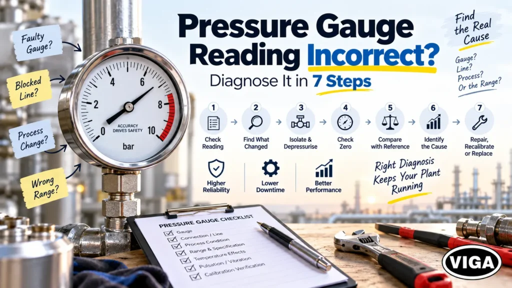
Pressure gauge reading incorrect diagnosis with seven troubleshooting steps
Blog

Pressure Gauge Reading Incorrect? Diagnose It in 7 Steps

Pressure Gauge Reading Wrong? How to Diagnose the Real Cause Table of Contents [-] Pressure Gauge Reading Incorrect? How to Tell Whether the Gauge, the Line or the Process Is at Fault An incorrect pressure gauge reading is one of the few plant faults where the wrong diagnosis costs more than no diagnosis at all. Swap a healthy instrument, and the defect that caused the error stays in the pipe. The replacement then reads wrong within weeks, the maintenance log records two failures where there was none, and the actual problem is now harder to see because the obvious suspect has already been eliminated. Understanding why a pressure gauge reads wrong therefore starts with a question that has nothing to do with the gauge: is the instrument reporting the process incorrectly, or is it reporting a process that genuinely is what it says it is? Before anything is opened Every diagnostic step below that involves a vent, a drain, a root valve or a process connection assumes the instrument has already been made safe. Isolate the gauge at the root valve and confirm the isolation actually holds. Depressurise through the designed vent or drain point, not by cracking a fitting. Verify zero pressure independently before any connection is loosened. Apply the site’s lock-out/tag-out procedure where it applies. Wear the PPE specified for the medium, including face protection where the process is hot, corrosive or above ambient temperature. Never loosen a gauge, adapter, vent plug or drain that may still hold pressure. Trapped pressure behind a blocked impulse line is a recognised hazard precisely because the gauge reads zero while the line is still live. Where the medium is steam, hot oil, oxygen, a toxic gas or a strong oxidiser, follow the plant’s permit system rather than treating this as routine maintenance. The rest of this guide assumes those conditions are met. Where the error actually lives Grouping causes this way is more useful than a flat list, because each group is confirmed by a different test. Category What it means Typical signature Gauge error Something inside the instrument has changed Pointer fails to return to zero; error grows or shrinks with pressure; reading differs rising vs falling Installation error Something between the tapping point and the gauge is interfering Reading is frozen, lagging, or consistently offset; reference gauge on the same tapping disagrees with the installed one Process condition The pressure genuinely is what the gauge says Both gauges agree; the change correlates with a plant event Specification error The gauge was never suited to the duty Gauge passes calibration and still gives a reading nobody can use A reading can be wrong while the gauge is entirely healthy. That is the point most troubleshooting misses. The diagnostic sequence Seven steps, in order. Stopping early is normal; most faults resolve by step five. Record what the gauge shows and what the plant expects, before anything is touched. A remembered value is not evidence. Ask what changed. A gauge that has read consistently for years and shifts over one weekend is more likely reporting a real process change than developing an internal fault on that schedule. New pump, altered valve position, fouled strainer, modified bypass, changed duty. Isolate and depressurise under the site procedure. Check zero. Where the design permits, vent the case as well. Note the pointer position and whether light tapping moves it. Compare against a calibrated reference gauge fitted at the same tapping point. Not a different branch of the same header. Characterise the error. Constant across the range, proportional to pressure, present only when hot, or intermittent? Each pattern points at a different group. Decide between recalibration, repair and replacement, using the framework near the end of this guide. Diagnostic Decision Tree Systematic Troubleshooting Workflow 1 Initial Trigger Reading appears incorrect 2 Preparation & Safety Isolate · Depressurise · Verify zero pressure Strictly adhere to plant and site-specific safety procedures. ? Does the pointer return to zero? NO Gauge Error Group Zero shift or permanent set of element Worn or seized movement mechanism Pointer slip on spindle Check: Inspect case vent first on liquid-filled gauges. YES Continue to On-Line Test Gauge rests normally. Proceed with dynamic reference checks. 3 Validation Step Compare with a calibrated reference gauge Must be performed AT THE SAME TAPPING POINT ? Reference Comparison Outcome Agrees Installation or Process Group Blocked or restricted impulse line Closed or throttled root valve Siphon empty / unsealed Elevation head pressure discrepancy Genuine unmonitored process change Disagrees Gauge Accuracy Group Instrument out-of-spec. Evaluate nature of deviation below. ? Does the error CHANGE with applied pressure? Error Changes Non-Linear / Dynamic Fault Span error Movement hysteresis Mechanical movement wear Internal calibration drift Error is Constant Fixed Offset Fault Zero offset error Reference/installation offset Missing static head correction ? Does the error change with TEMPERATURE? YES Thermal / Environmental Ambient temperature influence Process heat conducting through socket Direct solar radiation gain Case liquid fill viscosity changes NO Mechanical Action Thermal factors eliminated. Continue bench-level mechanical diagnosis and overhaul. Errors that originate in the gauge Zero shift, and why a pointer at zero proves less than it looks Two things are worth ruling out before concluding the instrument is damaged. The first is the case vent. Liquid-filled gauges are commonly supplied with the compensation vent closed so the fill survives transport, and the design intends it to be opened after installation. Left closed in a shed where the internal temperature rises through the day, the sealed case can pressurise against the measuring element and produce an offset that tracks ambient temperature. Opening the vent frequently collapses that error on the spot. VIGA’s guide to glycerine-filled pressure gauges covers the fill and vent behaviour in more detail. The second is mounting position. A gauge calibrated for one orientation and installed in another can show a small zero shift, and the effect is larger on liquid-filled cases because the fill column loads the movement differently. There is also a reading trap.

Scroll to Top