


Pressure Gauge Reading Wrong? How to Diagnose the Real Cause
Pressure Gauge Reading Incorrect? How to Tell Whether the Gauge, the Line or the Process Is at Fault
An incorrect pressure gauge reading is one of the few plant faults where the wrong diagnosis costs more than no diagnosis at all. Swap a healthy instrument, and the defect that caused the error stays in the pipe. The replacement then reads wrong within weeks, the maintenance log records two failures where there was none, and the actual problem is now harder to see because the obvious suspect has already been eliminated.
Understanding why a pressure gauge reads wrong therefore starts with a question that has nothing to do with the gauge: is the instrument reporting the process incorrectly, or is it reporting a process that genuinely is what it says it is?
Before anything is opened
Every diagnostic step below that involves a vent, a drain, a root valve or a process connection assumes the instrument has already been made safe.
- Isolate the gauge at the root valve and confirm the isolation actually holds.
- Depressurise through the designed vent or drain point, not by cracking a fitting.
- Verify zero pressure independently before any connection is loosened.
- Apply the site’s lock-out/tag-out procedure where it applies.
- Wear the PPE specified for the medium, including face protection where the process is hot, corrosive or above ambient temperature.
- Never loosen a gauge, adapter, vent plug or drain that may still hold pressure. Trapped pressure behind a blocked impulse line is a recognised hazard precisely because the gauge reads zero while the line is still live.
- Where the medium is steam, hot oil, oxygen, a toxic gas or a strong oxidiser, follow the plant’s permit system rather than treating this as routine maintenance.
The rest of this guide assumes those conditions are met.
Where the error actually lives
Grouping causes this way is more useful than a flat list, because each group is confirmed by a different test.
| Category | What it means | Typical signature |
|---|---|---|
| Gauge error | Something inside the instrument has changed | Pointer fails to return to zero; error grows or shrinks with pressure; reading differs rising vs falling |
| Installation error | Something between the tapping point and the gauge is interfering | Reading is frozen, lagging, or consistently offset; reference gauge on the same tapping disagrees with the installed one |
| Process condition | The pressure genuinely is what the gauge says | Both gauges agree; the change correlates with a plant event |
| Specification error | The gauge was never suited to the duty | Gauge passes calibration and still gives a reading nobody can use |
A reading can be wrong while the gauge is entirely healthy. That is the point most troubleshooting misses.
The diagnostic sequence
Seven steps, in order. Stopping early is normal; most faults resolve by step five.
- Record what the gauge shows and what the plant expects, before anything is touched. A remembered value is not evidence.
- Ask what changed. A gauge that has read consistently for years and shifts over one weekend is more likely reporting a real process change than developing an internal fault on that schedule. New pump, altered valve position, fouled strainer, modified bypass, changed duty.
- Isolate and depressurise under the site procedure.
- Check zero. Where the design permits, vent the case as well. Note the pointer position and whether light tapping moves it.
- Compare against a calibrated reference gauge fitted at the same tapping point. Not a different branch of the same header.
- Characterise the error. Constant across the range, proportional to pressure, present only when hot, or intermittent? Each pattern points at a different group.
- Decide between recalibration, repair and replacement, using the framework near the end of this guide.
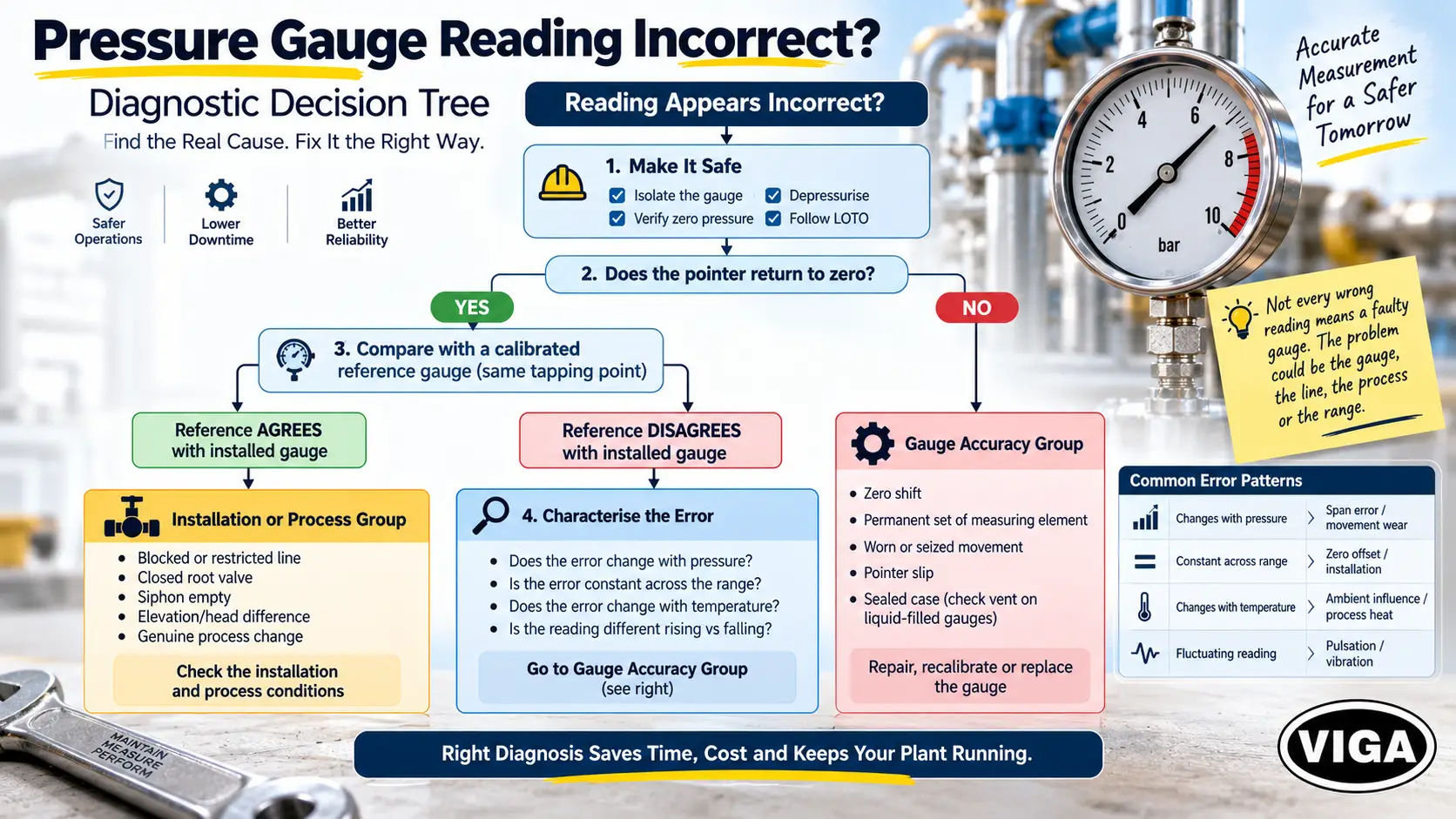
Diagnostic Decision Tree
Systematic Troubleshooting Workflow
Strictly adhere to plant and site-specific safety procedures.
- Zero shift or permanent set of element
- Worn or seized movement mechanism
- Pointer slip on spindle
Gauge rests normally. Proceed with dynamic reference checks.
- Blocked or restricted impulse line
- Closed or throttled root valve
- Siphon empty / unsealed
- Elevation head pressure discrepancy
- Genuine unmonitored process change
Instrument out-of-spec. Evaluate nature of deviation below.
- Span error
- Movement hysteresis
- Mechanical movement wear
- Internal calibration drift
- Zero offset error
- Reference/installation offset
- Missing static head correction
- Ambient temperature influence
- Process heat conducting through socket
- Direct solar radiation gain
- Case liquid fill viscosity changes
Thermal factors eliminated. Continue bench-level mechanical diagnosis and overhaul.
Errors that originate in the gauge
Zero shift, and why a pointer at zero proves less than it looks
Two things are worth ruling out before concluding the instrument is damaged.
The first is the case vent. Liquid-filled gauges are commonly supplied with the compensation vent closed so the fill survives transport, and the design intends it to be opened after installation. Left closed in a shed where the internal temperature rises through the day, the sealed case can pressurise against the measuring element and produce an offset that tracks ambient temperature. Opening the vent frequently collapses that error on the spot. VIGA’s guide to glycerine-filled pressure gauges covers the fill and vent behaviour in more detail.
The second is mounting position. A gauge calibrated for one orientation and installed in another can show a small zero shift, and the effect is larger on liquid-filled cases because the fill column loads the movement differently.
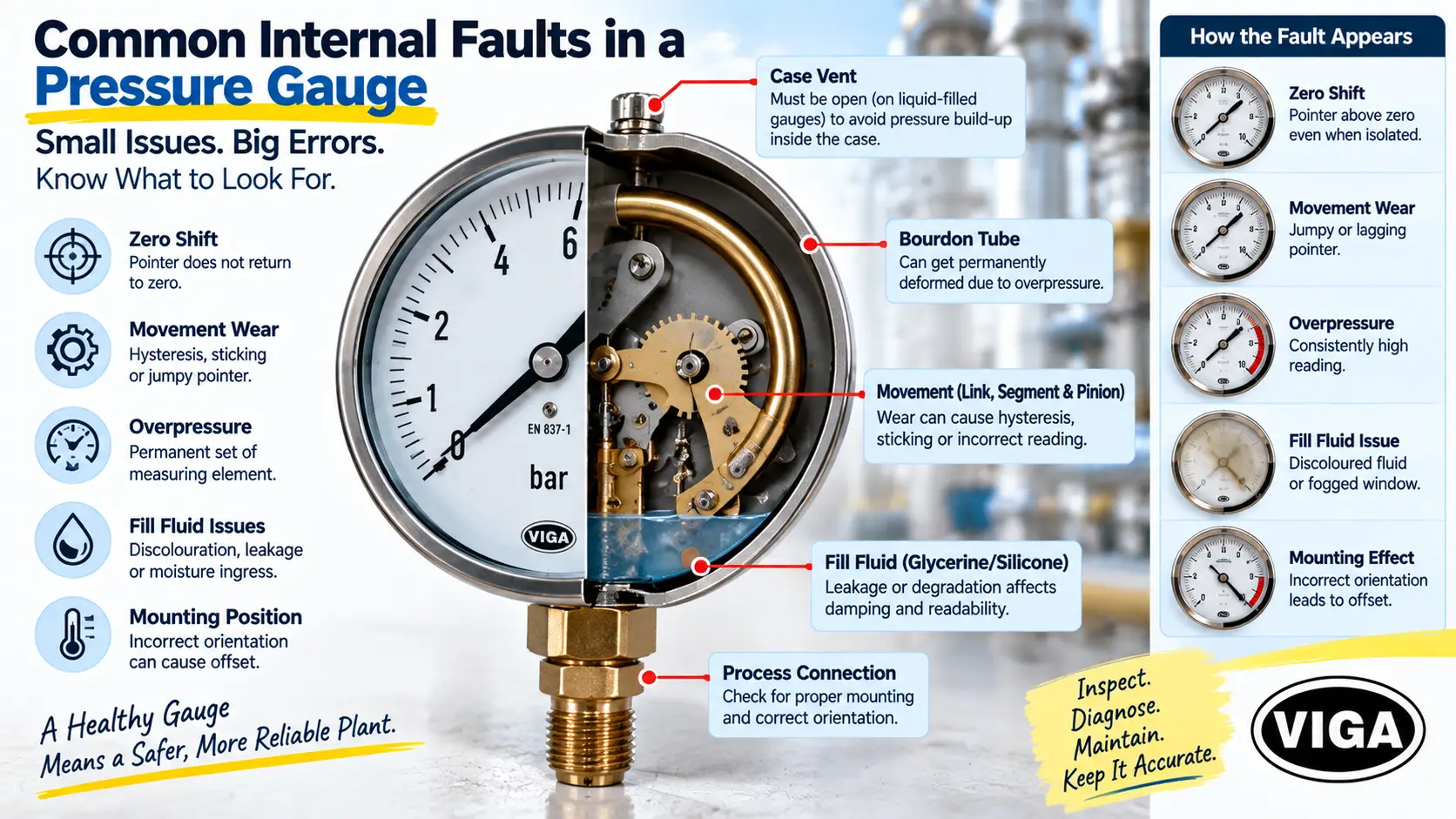
There is also a reading trap. Many industrial dials are fitted with a pointer stop pin at zero, so a pointer resting against that pin does not by itself confirm zero — it may be pressing against the pin from below. EN 837-1 test practice takes the indication after the gauge has been lightly tapped, which is a reasonable field habit for the same reason: friction in the movement can hold a pointer somewhere it would not otherwise sit.
Where a gauge offers an adjustable pointer or an external zero screw, use it only after linearity has been confirmed against a reference. Correcting the reading at zero does nothing to a span error, and the result is an instrument that appears trustworthy at the one pressure the plant never operates at.
Overpressure and permanent set of the measuring element
Once a Bourdon tube has been strained past its elastic limit it does not return to its original geometry. The zero shifts, the span distorts, and the deviation is not a clean constant that can be subtracted.
The permissible loading is not a single universal figure, and this is where specifications are most often misread. EN 837-1 distinguishes gauges that are full-scale loadable from those that are not, and the two behave differently:
- Instruments that are not full-scale loadable — often those with copper-alloy measuring elements — are commonly specified on manufacturer datasheets as steady load up to three-quarters of full scale value, fluctuating load up to two-thirds, and short-term load up to full scale value.
- Full-scale loadable instruments — typically stainless steel elements, and identified by a mark at the maximum scale value — are commonly specified as steady load equal to full scale value, fluctuating load 0.9 × full scale, and short-term 1.3 × full scale.
The widely quoted “75% steady, 65% fluctuating” figure belongs to the selection and installation guidance in EN 837-2 and to the first category above. Applying it to every gauge, or quoting 130% overload as a universal allowance, misstates what the instrument in front of you is rated for. Check the datasheet for the specific model.
Events that cause permanent set are usually brief and unobserved: a pump started against a closed discharge, water hammer from a fast-acting valve, hydrostatic testing carried out with the working gauge still in circuit, a purge cracked open at full line pressure, relief valve chatter on a hydraulic pack.
Typical field scenario: a workshop hydro-tests its own manifolds and leaves the working gauges connected. The test pressure is legitimate for the manifold and well outside the rating of the gauges. Afterwards a row of instruments on the same rig shows a similar upward zero offset, which looks like a batch quality problem and is in fact a single procedural one.
Permanent set is not repairable. Prevention is the useful part of the conversation: an overpressure protector or gauge saver on lines with known surge, a snubber or restrictor on pulsating discharge, and a range chosen with headroom for the real peak rather than the nominal duty.
Wear in the movement
The gear train (link, segment, pinion and hairspring) announces itself differently from every other cause on this list:
- the gauge reads differently rising than falling at the same pressure (hysteresis);
- the pointer advances in visible steps rather than smoothly;
- the pointer sticks, then jumps to catch up;
- tapping the case produces a repeatable change in the reading.
That last symptom is the quickest field indicator of mechanical slack, and no amount of re-zeroing addresses it. Confirmation takes a slow ramp against a reference, up through several points and back down through the same ones. A separation at mid-scale larger than the accuracy class allows condemns the instrument.
A related and easily missed failure is pointer slip on the spindle. Zero reads correctly, span does not, and the gauge looks healthy on the single check most technicians perform.
Fill fluid and case condition
Fill is a consumable, though it is rarely treated as one. Glycerine discolours under sustained heat and UV; the colour change alone does not shift the reading, but it eventually makes the dial unreadable, which is a functional failure regardless.
Fluid loss matters more. A leaking vent, a failed bezel crimp or a cracked window lets fill escape and moisture in. Damping is lost first, condensation appears next, and corrosion of the movement follows.
Two selection points are worth carrying into any replacement decision. Glycerine fills are commonly rated for ambient service down to around −20 °C, with silicone used where the ambient goes lower; a sluggish pointer on a cold morning that behaves normally by afternoon usually indicates fill viscosity rather than a sticking movement. And for oxidising media — oxygen, chlorine, hydrogen peroxide — glycerine and hydrocarbon-based fills are not appropriate. Those duties call for instruments cleaned for oxygen service, or a halocarbon-type inert fill, and this is a safety requirement rather than a preference.
Errors that originate in the installation or the process
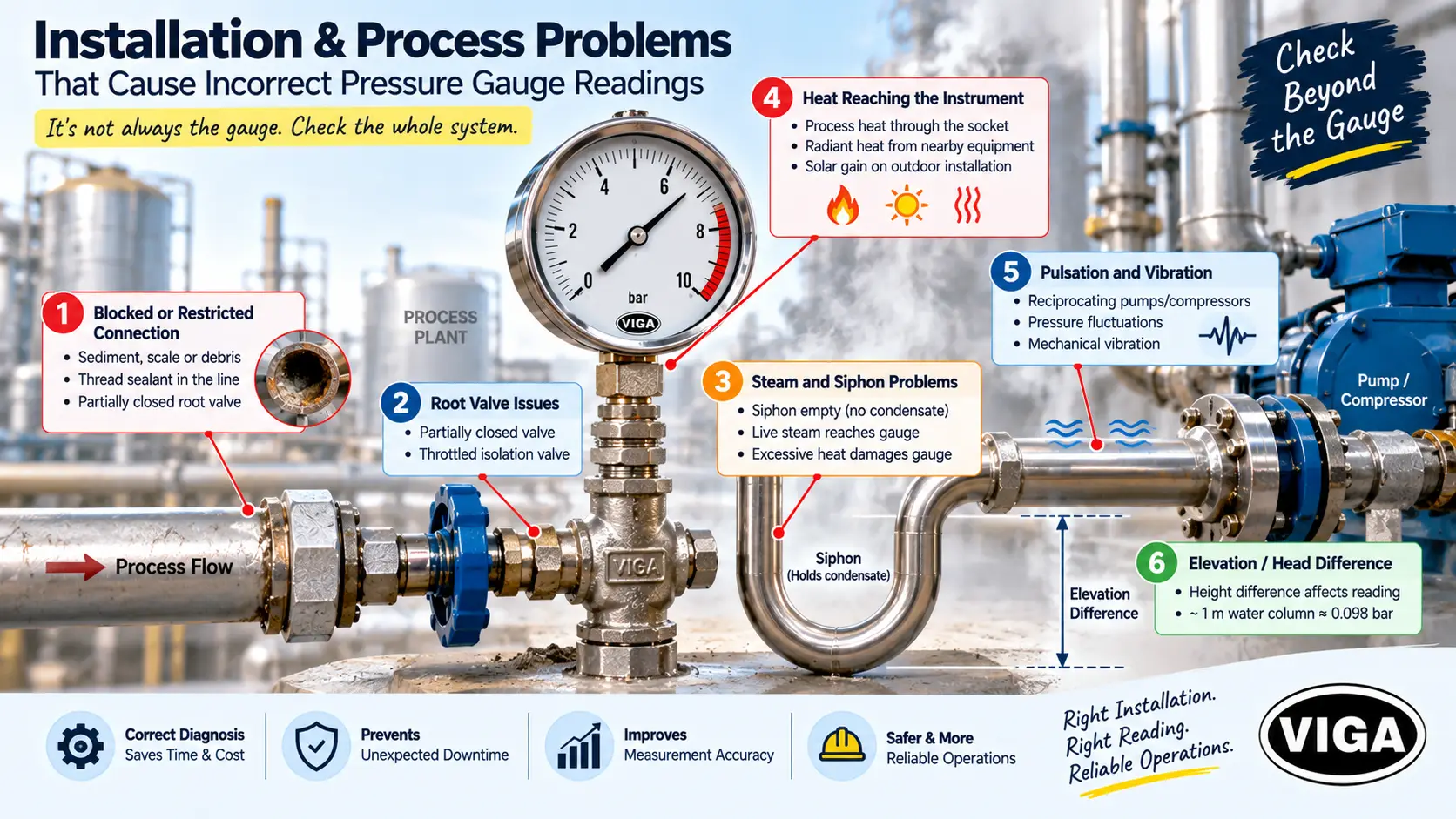
A restricted or blocked connection
When a pressure gauge needle is stuck at one value and does not respond to anything the plant does, the connection is among the first things to check.
Lines restrict for predictable reasons: settled sediment in raw water and effluent duty, scale in steam and boiler feed, crystallising or polymerising media in chemical service, hardened grease, overspray around finishing lines, and thread sealant pushed into the socket during a previous fitting. Outdoor lines in northern India can add frozen condensate on winter mornings, which clears by midday and makes the fault look intermittent.
A fully blocked line gives a frozen pointer. A partially restricted one is more deceptive: the gauge still moves, but lags the process or sits consistently low because it never equalises.
The root valve deserves the same suspicion. A partially closed or throttled isolation valve produces exactly the symptoms of a restricted line, and costs nothing to rule out.
Pulsation and vibration
A fluctuating reading on a reciprocating compressor, a positive-displacement pump or a hydraulic power pack is often the gauge doing its job on a genuinely pulsating pressure. The damage is cumulative rather than immediate: every cycle works the element and the gearing, and over months the instrument becomes less willing to settle.
Three countermeasures address different halves of the problem, which is why fitting only one often disappoints:
- Liquid filling damps pointer movement and lubricates the mechanism. It does not remove the pressure spikes.
- A snubber, restrictor or pulsation dampener flattens the peaks before they reach the element. This is the part that protects the gauge.
- A diaphragm seal with capillary, or remote panel mounting, is the answer where the instrument cannot survive at the machine at all.
Heat reaching the instrument
Mechanical gauges are calibrated at a reference temperature of 20 °C. Manufacturer datasheets referencing EN 837-1 commonly state a temperature influence of up to ±0.4% of span per 10 K of deviation from that reference, though the figure varies by model and some manufacturers publish different values — the datasheet is the authority, not a rule of thumb.
On a 0–16 bar instrument, a deviation of 25 K from reference at that coefficient is worth roughly 0.16 bar of additional error before anything else is considered. Enough to fail a tolerance check on a gauge with nothing wrong with it.
Three heat paths are worth separating. Process heat conducted through the socket, which changes the elastic behaviour of the measuring element and is addressed with a siphon or cooling element. Radiant heat from furnaces, quench tanks and heat-treatment lines, where a sheet-metal shield is often the whole fix. And solar gain on outdoor skids, which produces an error with a daily rhythm — if the reading is repeatably different at 3 p.m. and 8 a.m., start there.
Where the swing is unavoidable and the measurement matters, an electronic pressure transmitter with internal temperature compensation removes the problem instead of managing it.
Steam, and the state of the siphon
A siphon, whether pigtail or coil, is intended to hold a column of condensate between the steam and the measuring element. Commissioned dry, live steam reaches the element directly, the socket runs hot, the reading drifts and the instrument degrades from the inside.
If the socket is uncomfortably warm to the back of the hand, check the siphon before condemning the gauge.
Tapping point, elevation, and two gauges that disagree
Two instruments separated by a filter, a strainer, a long horizontal run or a change in height are not measuring the same pressure, and a real pressure drop is regularly mistaken for an instrument fault.
Elevation alone is measurable: roughly one metre of water column corresponds to about 0.098 bar. A gauge mounted two metres above its tap point on a water line will legitimately read around 0.2 bar lower than one at the tap.
Where two gauges disagree and the cause is unclear, swapping them between positions settles it in one move. If the discrepancy follows the position, it is the installation. If it follows the instrument, it is the gauge.
Errors that were designed in
Range
Accuracy for mechanical gauges is stated against full scale, not against the reading. That single fact accounts for a large share of “the gauge is not accurate” complaints raised on instruments performing exactly to specification.
Take a Class 1.0 instrument with a 0–25 bar range. Permitted error is ±0.25 bar anywhere on the dial.
- Operating at 20 bar: 0.25 ÷ 20 × 100 = ±1.25% of the reading.
- Operating at 2 bar: 0.25 ÷ 2 × 100 = ±12.5% of the reading.
Same instrument, same compliance, and at the low end the indicated number is close to meaningless.
Over-ranging is usually well intentioned. Procurement standardises on one range to simplify spares; an engineer specifies high after an overpressure incident. The outcome is a store full of compliant, unusable instruments. Position the normal operating pressure so it falls in the readable middle portion of the dial, and check the real peak — startup, pump shut-off head, relief setting, pulsation — rather than the nominal duty. VIGA’s pressure gauge selection guide works through the selection factors in sequence.
Dial size belongs to the same decision. A 63 mm dial read from four metres across a walkway needs coarser graduations than one read at arm’s length on a bench.
What the accuracy class actually guarantees
EN 837-1 defines seven accuracy classes for Bourdon tube gauges: 0.1, 0.25, 0.6, 1, 1.6, 2.5 and 4. The number is the maximum permissible error expressed as a percentage of full scale value, and a lower number means a tighter instrument. In India, IS 3624 covers pressure and vacuum gauges for the same procurement purpose, and many gauges sold here are marked to more than one standard.
One difference matters when comparing datasheets across regions: EN 837 applies its class limit across the dial, whereas ASME B40.100 grades are commonly described with segmented tolerances that are tighter through the middle of the range and looser at the extremes. Comparing a class number against a grade letter without checking which convention applies produces a false equivalence.
Which pressure is being measured
Two instruments can be entirely healthy and still disagree, because they are referenced differently.
- Gauge pressure is measured relative to ambient atmospheric pressure. Zero on the dial means atmospheric.
- Absolute pressure is measured from a sealed vacuum reference. An absolute instrument reads roughly 1 bar where a gauge instrument reads zero.
- Differential pressure is the difference between two points and says nothing about the pressure at either one. A filter DP gauge and a line gauge are not comparable readings.
- Vacuum instruments read below atmospheric, and compound instruments span both sides of atmospheric on one dial.
Before treating a discrepancy as a fault, confirm both instruments share a reference. Altitude adds a further nuance for absolute-versus-gauge comparisons, since ambient pressure itself is not a fixed number.
Verifying a gauge properly: what a calibration actually tests
A single-point check against a reference tells you very little. A calibration worth acting on establishes several things at once.
The reference. A master or reference gauge with a valid certificate, traceable through an accredited laboratory. In India that means ISO/IEC 17025 accreditation with NABL scope covering the relevant pressure range. A common working guideline is that the reference should be meaningfully more accurate than the instrument under test; VIGA’s master gauge calibration guide discusses the ratio conventions.
Zero check. Recorded before adjustment, not after.
Rising test. Applied pressure increased through several defined points. EN 837-1 test practice uses points at 0, 25, 50, 75 and 100% of full scale as a minimum, with readings taken after light tapping.
Falling test. The same points approached from above. Recording only the rising sequence conceals hysteresis, which is precisely the error that identifies a worn instrument.
Hysteresis and repeatability. The separation between rising and falling readings at each point, and the consistency of repeated runs, are both meaningful independently of the raw error.
Allowable error. Compared against the stated accuracy class, expressed against full scale.
Documentation. As-found and as-left values recorded separately, so drift between intervals can be tracked. File the certificate against the tag number rather than the gauge serial, because tags outlive instruments.

A worked example. A Class 1.0 gauge on a 0–25 bar range is allowed ±0.25 bar. Found reading 2.15 bar against a reference at 2.00 bar, the error is +0.15 bar — inside class, and therefore a pass. Expressed against the reading it is +7.5%, which is why the same instrument can be simultaneously compliant and unfit for that duty. Compliance and usefulness are separate judgements.
On intervals: there is no universal recalibration period. The interval is set by the consequence of an undetected error, the operating environment, any applicable regulatory or customer requirement, and the instrument’s own drift history. Plants commonly review at six or twelve months for process instruments and shorten that for safety-related duty, but the defensible answer comes from a documented risk assessment rather than a supplier’s rule of thumb. One case is unambiguous: any gauge known to have experienced an overpressure event should be verified immediately, whatever the schedule says. Step-by-step method is covered in VIGA’s pressure gauge calibration guide.
Eight troubleshooting mistakes worth avoiding
- Replacing the gauge before checking the line. The most expensive order in which to do things, because it destroys the evidence.
- Re-zeroing before checking span. Produces an instrument that reads correctly at a pressure nobody uses.
- Comparing gauges at different tapping points. Pressure drop and elevation are not instrument errors.
- Specifying an oversized range for safety. Compliant, and unreadable at the operating point.
- Treating a liquid-filled gauge as a complete pulsation solution. Filling protects the mechanism; a snubber addresses the spikes.
- Opening a connection that may still be pressurised. A blocked line can read zero while holding pressure.
- Leaving working gauges connected during hydrostatic testing. A recurring, entirely avoidable cause of permanent set.
- Ignoring ambient temperature and mounting orientation. Both produce errors that look like calibration faults and are not.
Recalibrate, repair or replace
The decision depends on gauge construction, service criticality and the manufacturer’s own service position. As a framework:
Recalibrate when the instrument is mechanically sound, the error sits within limits that adjustment can correct, and traceable documentation is required for the process or the auditor.
Repair when the instrument carries genuine economic repair value: larger process gauges, test gauges, and diaphragm-seal assemblies where the seal, capillary and process connection remain sound. In those cases, only movement or dial components need attention. A repair is not complete until the instrument has been recalibrated.
Replace when any of the following applies:
- the measuring element shows permanent deformation from overpressure;
- the movement is badly worn, seized or corroded;
- fill has been lost and moisture has reached the mechanism;
- corrosion has compromised the socket, wetted parts or case integrity;
- the dial is no longer legible;
- the instrument fails at multiple calibration points beyond what adjustment can correct;
- the application or specification was wrong from the start, in which case replacement should be a re-specification rather than a like-for-like swap;
- calibration, removal, transport and downtime together approach the delivered cost of a new instrument.
That last line settles most decisions on smaller industrial dials before the technical argument begins.
DIAGNOSTIC TROUBLESHOOTING TABLE
Pressure Gauge Troubleshooting Guide
| Symptom | First Check | Likely Cause | Confirmation | Corrective Action |
|---|---|---|---|---|
| Pointer above zero when isolated and vented | Case vent plug on liquid-filled gauges | Sealed case pressure, or permanent set of the element | Open the vent; if the offset persists, ramp against a reference | Replace if set; add gauge saver or snubber |
| Pointer below zero at rest | Tap the case lightly | Movement wear or pointer slip on the spindle | Rising and falling check against a reference | Replace |
| Pointer stuck at one value | Root valve position, then crack the vent at the gauge | Blocked line, closed valve, or seized movement | No flow on a line that should be live confirms blockage | Clear the line at shutdown; consider a diaphragm seal |
| Reads low, zero correct | Root valve and line restriction | Partial restriction or throttled isolation | Reference gauge on the same tapping | Clear the restriction; verify valve position |
| Reads high, zero correct | Socket temperature by hand | Process heat, empty siphon, or head correction | Check the siphon; check elevation difference | Fill or refit the siphon; apply head correction |
| Reading fluctuates continuously | Source of pulsation | Reciprocating pump or compressor, or transmitted vibration | Compare against a damped reference | Liquid fill combined with a snubber or restrictor |
| Rising and falling readings differ | Slow ramp both directions | Hysteresis from worn movement or fatigued element | Multi-point calibration check | Recalibrate if within class; replace if not |
| Error changes with ambient temperature | Time of day and sun exposure | Ambient influence, solar gain, or sealed case | Shade the instrument and re-read after equalising | Sun shield, remote mount, or a fill suited to the range |
| Window fogged, fill discoloured or low | Visual inspection | Seal failure and moisture ingress | Fill level and dial legibility | Replace |
| Sluggish response in cold weather only | Ambient temperature vs fill rating | Fill viscosity below its practical range | Compare response later in the day | Specify silicone fill for the ambient range |
| Sudden shift after a valve operation | Recent plant events | Water hammer or overpressure | Zero check after isolation | Replace; add snubber and restrictor |
| Passes calibration, reading still unusable | Where the pointer sits on the dial | Range mis-selection | Recompute class error as a percentage of the reading | Re-specify to place normal pressure mid-dial |
| Two gauges on one system disagree | Tapping locations and elevation | Head difference, pressure drop, or different pressure reference | Swap the two instruments between positions | Correct for head; confirm both share a reference |
| New gauge reads incorrectly out of the box | Vent, range, connection and reference | Transport shock, wrong specification, or unopened vent | Bench check against a master | Open the vent; verify specification; return if faulty |
FAQ
Q1. Why is my pressure gauge reading wrong?
Four groups of causes are possible, and they are separated by different tests. The gauge itself may have shifted zero, taken overpressure damage, worn its movement, drifted, or lost its fill. The installation may be restricting or blocking the pressure signal. The process may genuinely have changed. Or the gauge may never have been suited to the duty. Start by isolating and depressurising the instrument safely, check whether the pointer returns to zero, then compare against a calibrated reference at the same tapping point.
Q2. Why does a pressure gauge read high or low?
The direction is a useful clue. Permanent deformation of the measuring element after overpressure tends to shift the indication upward. Restricted or blocked connections, and worn gearing, more often produce a low or lagging reading. Heat reaching the measuring element through the socket, including from an empty steam siphon, tends to push the reading up. A gauge mounted well above its tapping point on a liquid line will read low by the liquid head, which is not an error at all.
Q3. Why is the pressure gauge needle stuck?
A needle that holds one value regardless of what the plant does usually indicates a blocked or restricted connection, a closed root valve, or a seized movement. Check the valve position first, then vent at the gauge under the site procedure. If nothing releases on a line that should be live, the obstruction is external and the instrument may be serviceable. If the line vents freely and the pointer stays put, the movement has failed.
Q4. Why does a pressure gauge fluctuate?
Usually because the pressure genuinely is fluctuating. Reciprocating pumps and compressors produce real pulsation, and mechanical vibration through rigid pipework adds to it. Neither is an instrument fault, but both shorten instrument life. A liquid-filled gauge combined with a snubber or restrictor addresses both halves; relocating the instrument with a diaphragm seal and capillary is the option where the environment is too severe.
Q5. Why does the gauge not return to zero?
On liquid-filled instruments, check the case vent before anything else, since a sealed case can hold pressure against the measuring element. Confirm the mounting orientation matches what the gauge was calibrated for. Be aware that many dials carry a pointer stop pin, so a pointer resting at zero does not by itself confirm a correct zero. If those are ruled out, the element or the movement has taken a permanent change and the instrument needs assessment against a reference.
Q6. How do I check whether a pressure gauge is accurate?
Compare it against a calibrated reference gauge with a valid traceable certificate, applied at the same tapping point or on a bench. Take readings at several points rising, then at the same points falling, tapping the instrument lightly before each reading. Compare the largest deviation against the accuracy class, remembering that the class is a percentage of full scale rather than of the reading.
Q7. How often should a pressure gauge be calibrated?
There is no single correct interval. It follows from the consequence of an undetected error, the severity of the service, any regulatory or customer requirement that applies, and the instrument’s own drift history. Many plants review process instruments at six or twelve months and shorten that for safety-related duty, but the interval should come from a documented assessment rather than a default. Any gauge known to have seen an overpressure event should be checked immediately.
Q8. Can a pressure gauge be repaired, or should it be replaced?
Both are possible and the economics usually decide. Permanent deformation of the measuring element is not repairable. Worn movements, damaged pointers and degraded dials can be repaired on instruments that justify it: larger process gauges, test gauges, and diaphragm-seal assemblies where the seal and capillary remain sound. On smaller industrial dials, repair labour plus the mandatory recalibration often meets or exceeds the cost of a new instrument.
Replacement, selection and calibration support
Diagnosis usually ends in one of two places: an installation correction that costs very little, or a replacement instrument that needs to be specified correctly rather than matched to what was there before.
VIGA supplies pressure instrumentation from Chawri Bazar, Delhi, to industrial users across Delhi NCR, and can help with range and accuracy-class selection, fill and connection choice, protection accessories such as siphons, snubbers, gauge savers and diaphragm seals, and arranging calibration support.
As an authorised distributor, VIGA supplies WIKA, Mass, Switzer and Indfos pressure instrumentation with full model traceability and documentation. As a manufacturer, VIGA produces its own VIGA and AIRCHAMP branded pressure and vacuum gauges in India.
Vinod Gautam Sales (VIGA) 20 Chawri Bazar, Delhi 110006 Phone: +91 11 4302 5959 · Email: [email protected]
Sending the tag number, range, connection size and a photograph of the dial is usually enough to establish whether the instrument needs replacing or the installation needs correcting.