April 2026

What is Thermocouple Types, Diagram, Working Principle & Uses
Blog

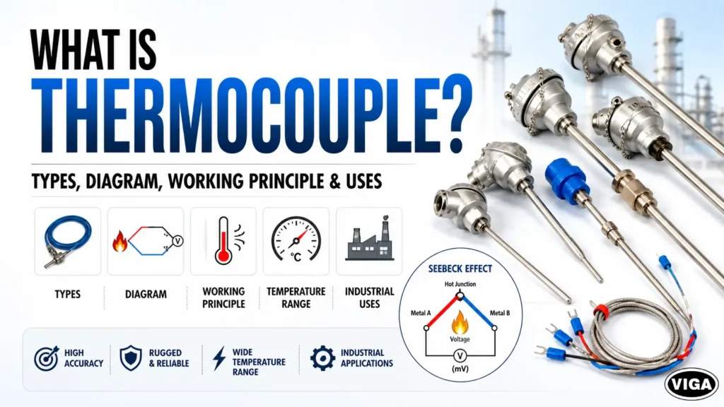
What is Thermocouple? Types, Diagram, Working Principle & Uses

Table of Contents [-] Forget fragile glass thermometers. A thermocouple is an industrial temperature measurement sensor built to survive. It uses two different metal wires welded at a single tip. Heat that junction. It instantly spits out a tiny voltage signal—the Seebeck effect in action. Pure physics powering heavy industry. Understanding the Industrial Thermocouple Sensor Heat runs the show in heavy manufacturing. If your reactor runs too cold, the chemical batch dies. If a blast furnace gets too hot? Liquid steel eats right through the floor. You need hardware that refuses to fail under extreme pressure. Too hot, and steel melts through the furnace floor. You need a sensor that survives hellish conditions, costs pennies on the dollar, and delivers fast, reliable data to your control systems. This is not a delicate laboratory instrument. It is a workhorse. It sits inside roaring incinerators, pressurized chemical vats, and freezing cryogenic chambers. Unlike standard thermometers that use expanding liquids, a thermocouple relies entirely on solid-state physics. Two different metals. One connection point. Heat it up, and it spits out a millivolt (mV) signal. The design is straightforward yet highly resilient, relying purely on solid-state physics to generate a millivolt (mV) signal when heated. Plant managers and instrumentation engineers rely on the thermocouple temperature sensor because it works when everything else fails. It has no moving parts. It requires no external power source to generate its primary signal. It is completely self-powered by the thermal energy it measures. If you are running a manufacturing plant, an oil refinery, or a commercial bakery, you are using these devices right now. But simply buying a sensor off the shelf is a recipe for disaster. You need to understand the physics, the metal combinations, and the exact failure modes. The Physics Under the Hood: Thermocouple Working Principle How does heating two pieces of metal create electricity? While it might seem counterintuitive, this process is governed by fundamental thermodynamics. To understand the thermocouple working principle, we have to look at electrons. When you heat a metal, the electrons at the hot end gain kinetic energy. They start bouncing around rapidly. Because they are highly energized, they naturally diffuse toward the cooler, less energetic end of the wire. This creates a tiny electrical imbalance. The Seebeck Effect: The Engine of Temperature Measurement In 1821, a physicist named Thomas Johann Seebeck discovered something fascinating. If you take two different conductive metals (let’s say iron and copper), join them at one end, and apply heat to that junction, a continuous electrical current flows through the circuit. Why two different metals? This material difference is the core of the measurement. Different metals have different atomic structures. Their electrons react differently to heat. If you used two wires made of the exact same copper alloy, the electron flow in both wires would cancel each other out. Net voltage: zero. But by using dissimilar metals—like Nickel-Chromium paired with Nickel-Alumel—the electrons in one wire move at a different rate than the other. This creates a measurable voltage potential at the open end of the circuit. We measure this output in millivolts (mV). As the temperature rises, the millivolt signal increases. A PID controller or PLC reads this tiny voltage, runs it through a specific algorithm based on the metal types, and converts it into a readable temperature on your screen. Cold Junction Compensation (CJC): The Hidden Hero A thermocouple does not actually measure absolute temperature. It measures a temperature differential. It measures the difference between the hot end (the measurement junction inside your furnace) and the cold end (the reference junction where the wires connect to your reading instrument). If the ambient temperature around your reading instrument changes, your entire temperature reading will be completely wrong. How do we fix this? Cold Junction Compensation (CJC). Modern thermocouple readers contain a secondary, highly sensitive internal thermometer (usually a thermistor or RTD) right at the connection terminals. This internal sensor measures the exact ambient temperature at the connection block. The microprocessor then mathematically adds this ambient temperature back into the equation. Expert Pro-Tip: “Never ignore your cold junction. I’ve seen process engineers tear apart a massive boiler system because they thought the internal temperature was dropping. The boiler was fine. The air conditioning in the control room had failed, heating up the cold junction and throwing off the entire differential reading. Always verify your CJC.” The Big League: Thermocouple Types Chart and Temperature Ranges Not all metals survive extreme heat. If you drop a copper wire into a glass-melting furnace, it vaporizes. This is why we have distinct thermocouple junction types categorized by letter designations. The letter dictates the exact metal alloys used. Choosing the right type is the difference between an accurate reading and a catastrophic system failure. Thermocouple Types Comparison Table Sensor Type Positive Wire (+) Negative Wire (-) Typical Temperature Range Best Industrial Application Type K Chromel (Ni-Cr) Alumel (Ni-Al) -200°C to +1260°C General purpose, Refineries, High heat Type J Iron (Fe) Constantan (Cu-Ni) 0°C to +760°C Plastics industry, Vacuum applications Type T Copper (Cu) Constantan (Cu-Ni) -200°C to +350°C Food processing, Cryogenics, HVAC Type E Chromel (Ni-Cr) Constantan (Cu-Ni) -50°C to +900°C Power plants, High-accuracy needs Type N Nicrosil (Ni-Cr-Si) Nisil (Ni-Si-Mg) -270°C to +1300°C High-temp nuclear, Furnace profiling Type S Platinum-10% Rhodium Platinum 0°C to +1480°C Biotech, Glass industry, Calibration labs Type R Platinum-13% Rhodium Platinum 0°C to +1480°C High-temp recovery, Ceramics Type B Platinum-30% Rhodium Platinum-6% Rhodium +870°C to +1700°C Steel production, Extreme heat Deep Dive: Base Metal Thermocouples Base metal thermocouples are the most widely deployed sensors in standard manufacturing, handling the vast majority of routine industrial tasks cost-effectively. 1. K Type Thermocouple: The Industry Standard If you blindly pull a sensor out of a factory toolkit, it is probably a Type K. Made from Chromel and Alumel, it offers an incredible temperature range (-200°C to +1260°C). It resists oxidation at high temperatures beautifully. Watch out for “Green Rot.” If you expose a Type K to a marginal

Pressure Sensor Explained Types, Working Principle & Applications
Blog

Pressure Sensor Explained: Types, Working Principle & Applications

Table of Contents [-] A pressure sensor detects physical force from liquids or gases and translates it into an electrical signal (such as a 4-20mA loop). In industrial automation, these instruments are critical for controlling valves, preventing pump cavitation, and monitoring flow rates via Programmable Logic Controllers (PLCs) and Variable Frequency Drives (VFDs). Specifying the wrong sensor type or output signal can result in control system failures, costly downtime, or catastrophic equipment damage. This guide breaks down the core working principles, technologies (piezoresistive, capacitive, strain gauge), and exact specifications required for harsh manufacturing environments. Terminology: Pressure Sensors vs. Transducers vs. Transmitters The industry uses a lot of terms interchangeably. This creates massive confusion. When someone on the floor yells that they need a new “pressure sensor,” they usually mean something else. Let’s clarify the hardware. 1. The Bare Pressure Sensor This is just the raw sensing element. It is a tiny piece of silicon or a bare metal diaphragm. It has no protective housing. It has no smart electronics. If you buy just a “sensor,” you are usually an OEM building your own circuit boards. 2. The Pressure Transducer Take that raw sensor. Put it inside a stainless steel housing. Add a basic circuit board. Now you have a transducer. It outputs a very weak electrical signal—usually raw millivolts (mV) or a low-level voltage like 0-5V. These are fine for clean laboratories. They are terrible for noisy factory floors. 3. The Pressure Transmitter This is the heavy artillery. It is a transducer packed with advanced amplification electronics. It takes that tiny millivolt signal, cleans it up, compensates for temperature shifts, and boosts it into an industrial-grade signal like a 4-20mA current loop. When you are buying hardware for an oil rig, a water treatment plant, or an automated assembly line, you are buying a transmitter. Period. How Pressure Sensors Work: Diaphragm Deflection and the Wheatstone Bridge So, how does physical water pressure turn into numbers on a computer screen? It comes down to one simple concept: microscopic bending. Every industrial pressure sensor relies on a sensing element. Usually, this is a very thin diaphragm. Think of it like the skin of a drum. Fluid or gas enters the process port of the sensor and pushes against this diaphragm. The diaphragm bends. We are not talking about massive movement here. The deflection is microscopic. It is measured in microns. But that tiny flex is all we need. Attached to the back of this diaphragm is an electrical circuit, almost always configured as a Wheatstone bridge. This is a diamond-shaped circuit made of four resistors. When the diaphragm is perfectly flat (zero pressure), the electrical resistance is perfectly balanced. When the fluid pushes the diaphragm, it bends the resistors. Stretching a resistor makes it longer and thinner, which increases its electrical resistance. Compressing it decreases the resistance. This mechanical stress imbalances the Wheatstone bridge. The bridge then spits out a tiny voltage drop. The harder the fluid pushes, the more the diaphragm bends, the more the resistance changes, and the higher the voltage output becomes. The onboard microprocessor reads this exact voltage, runs it through some math, and sends a clean signal to your control panel. Critical Note on Temperature Compensation: Temperature is the enemy of accuracy. Heat naturally changes electrical resistance. If your sensor lacks active temperature compensation, a 30-degree swing in your plant’s ambient temperature will artificially change the sensor’s output, tricking your PLC into thinking the pressure changed. Always check the spec sheet for “temperature compensated range.” Core Pressure Sensor Technologies You cannot use one type of sensor for every job. The internal mechanics dictate where the device survives and where it dies. Here are the three technologies that actually matter. 1. Piezoresistive Pressure Sensors (The Workhorse) Piezoresistive sensors are the standard workhorse for general process control and water lines. Instead of bonded metal resistors, these utilize a solid piece of silicon. Bending the silicon alters its atomic structure and electrical conductivity, providing incredibly fast sub-millisecond response times and high accuracy. However, bare silicon degrades rapidly when exposed to water or harsh chemicals. To prevent failure, industrial models utilize a stainless steel isolation diaphragm filled with non-compressible transfer oil to protect the silicon element while maintaining measurement accuracy. 2. Capacitive Pressure Sensors (The Ghost Hunters) Capacitive sensors ignore electrical resistance completely. They measure electrical capacitance. Inside the housing, there are two conductive plates. One is fixed in place. The other plate is the flexible diaphragm. There is a tiny gap between them. When pressure pushes the flexible plate closer to the fixed plate, the capacitance of the circuit increases. While capacitive sensors are physically bulkier than other options, they offer extreme low-pressure sensitivity. They can easily measure fractions of an inch of water column, making them unmatched for monitoring precise draft pressures inside industrial chimneys or tracking delicate airflow in HVAC ductwork. 3. Strain Gauge Pressure Sensors (The Tanks) This is older technology, but it refuses to die. A metal foil pattern is bonded directly to a thick metal diaphragm. It relies on pure brute force. While this technology is less sensitive and more prone to zero drift over long periods, it offers unmatched brute-force durability. If you put a piezoresistive silicon sensor on a heavy stamping press, the violent shockwaves will shatter the chip into dust. A bonded foil strain gauge, however, effortlessly absorbs extreme shock and high-impact vibration without failing. Quick Technology Comparison Technology Type Best Feature Biggest Weakness Primary Industrial Use Case Piezoresistive High accuracy, fast response Silicon easily damaged by shock General process control, water lines, pneumatics Capacitive Extreme low-pressure sensitivity Physically larger footprint HVAC ductwork, cleanrooms, level measurement Strain Gauge Handles violent shock & vibration Lower accuracy, slower response Heavy hydraulics, excavators, stamping presses Reference Points: Gauge, Absolute, and Differential Pressure You have selected your technology. Now you need to define your reference point. Pressure is just a measurement of force compared to something else. What is your “something else”? Gauge Pressure Sensor

Industrial Temperature Switches Working Principle & Types
Blog

Industrial Temperature Switches: Working Principle & Types

Table of Contents [-] What is an industrial temperature switch? An industrial temperature switch is an electromechanical or solid-state safety device that monitors thermal limits in process automation. When a system exceeds a calibrated setpoint, it instantly opens or closes an electrical circuit to trigger alarms or shut down heavy machinery. Heat kills machinery. It is that simple. You do not get a polite warning when a heavy compressor’s oil cooler fails. You do not get a heads-up before a pressurized boiler loop hits its absolute metallurgical limit. You just get a massive repair bill. The metal warps. The bearings seize. Production stops dead. If you manage a process plant or oversee heavy automation, hoping for the best is not an engineering strategy. You cannot rely on manual observation. You need fail-safe hardware that reacts in milliseconds. This guide strips away the catalog jargon. We are looking at the raw physics happening inside the switch casing. You will learn exactly how to match internal contact logic and sensing technologies to your specific plant floor. Buying the wrong switch—or confusing it with a standard thermostat—will cause rapid-fire false trips and destroy your electrical contactors. Let’s look at the hardware that actually protects your facility. Before you specify another switch for your pneumatic automation or boiler loop, you need to understand the raw physics inside the casing. In This Engineering Guide: The Raw Physics: Actuation, Set Points, and the Deadband Trap. Hardware Breakdown: Bimetal, Capillary, and Solid-State Electronic. The Industrial Trenches: Deployments in Boilers, Compressors, and HVAC. The Procurement Checklist: How to specify wetted parts and IP ratings. The Hard Truth: Why a switch is not a thermostat or a sensor. A temperature switch is a specialized electromechanical or solid-state safety device that monitors thermal limits. When a process breaches a specific heat threshold, it instantly opens or closes an electrical circuit to trigger alarms, shut down machinery, or start cooling cycles, preventing catastrophic equipment failure. Walk onto any heavy manufacturing floor. The noise is deafening. The machinery is massive. But the real enemy is completely silent. It is heat. Uncontrolled thermal energy is the fastest way to destroy millions of dollars of capital equipment, and it happens faster than a human operator can hit an emergency stop button. You cannot rely on manual observation to catch thermal runaway. You need automated, instantaneous hardware. That is exactly what temperature switches do. They sit on your process lines, inside your compressor housings, and bolted to your boiler tanks, waiting for the exact millisecond things get too hot. Then, they kill the power. We are going to break down exactly how this hardware works. We will strip away the marketing fluff and look at the actual physics happening inside the casing. If you are an instrumentation engineer or a plant manager trying to stop burning through your maintenance budget on blown seals and seized motors, pay attention. Buying the wrong switch is just as bad as having no switch at all. The Raw Physics: Temperature Switch Working Principle Stop thinking of these devices as black boxes. To troubleshoot them, you need to understand the mechanical reality of what happens when they get hot. The foundational temperature switch working principle is entirely based on converting raw thermal energy into either physical mechanical motion or a measurable shift in electrical resistance. When your target process—be it a pool of lubricating oil or a high-pressure steam line—heats up, that energy transfers into the switch’s sensing element. The element reacts. Once that reaction hits a calibrated threshold (your set point), it physically forces a microswitch to actuate. It snaps open. Or it snaps shut. It is a harsh, binary action. The Hysteresis Trap: Set Points vs. Deadbands Engineers screw this up constantly. The temperature set point adjustment is just the start. You dial in your limit—say, 180°C. The temperature hits 180°C, the switch trips, and your emergency cooling fan kicks on. But what happens next? The process cools down to 179°C. Does the switch reset and turn the fan off? If it does, you have a massive problem. The temperature will immediately bump back to 180°C a second later, and the fan kicks on again. This rapid on-off-on-off cycle is called “short-cycling.” It will absolutely destroy your contactors and burn out your fan motor in a matter of days. This is why deadband (hysteresis) exists. Deadband is the required temperature gap between the actuation point and the reset point. You set it to trip at 180°C, but you engineer the deadband so it does not reset until the temperature drops down to 160°C. Expert Pro-Tip: Never specify a switch without calculating your required deadband first. In heavy pneumatic automation setups, the thermal inertia of a massive compressor block means heat dissipates slowly. A tight deadband will cause the main drive motor to chatter. Specify a wide, adjustable deadband for large rotating equipment to protect your electrical switchgear. Wiring the Logic: NO/NC Contact Configurations The switch itself is dumb. It just moves. The electrical contacts inside dictate the actual safety logic of your plant. You have two choices. Normally Open (NO): The electrical circuit is broken. Power cannot flow. When the switch hits its high-temperature limit, the internal mechanism slams the contacts shut. Power flows. You use this configuration to turn things on in an emergency. Sirens. Flashing lights. Emergency exhaust louvers. Normally Closed (NC): The circuit is complete under normal, healthy conditions. Power flows freely to keep your machine running. When the heat spikes to a dangerous level, the switch forces the contacts apart. Power is instantly severed. This is the only way you should wire a high temperature cut off switch. It is a fail-safe. If the wire gets cut accidentally, the machine shuts down. The Hardware Breakdown: Types of Industrial Temperature Switches A chemical processing plant is not an office building. You cannot slap commercial-grade plastic parts onto a vibrating generator skid and expect them to survive. You have to match the internal sensing technology

Flow Switches Working Principle, Types & Troubleshooting
Blog

Flow Switches: Working Principle, Types & Troubleshooting

What exactly is a flow switch? Think of it as a pipeline’s emergency brake. It’s a mechanical or electronic safety guard bolted directly into your piping to watch the movement of liquids or gases. It doesn’t just watch, though. It physically stops disasters. If the flow rate dips too low or spikes too high, it snaps an electrical contact shut. Instantly. Pumps power down. Alarms blast. Backup systems kick in. Quick Technical Summary: Core Job: A physical fail-safe tracking liquid or air speed. The Big Difference: Sensors give you continuous analog numbers. Switches just give you a hard Yes or No (a binary dry contact closure). Best For: HVAC chillers, centrifugal pumps, and fire protection systems. Pump cavitation is an expensive mistake. In power infrastructure, pneumatic automation, or heavy manufacturing plants, Industrial pipelines do not fail politely; they fail violently. If you manage heavy infrastructure, you know that relying solely on software to monitor your piping is a gamble. You need physical, mechanical fail-safes. Flow switches provide exactly that. They are binary. They do not care about trend lines or data logs. They care about one thing: is the fluid moving fast enough to keep this equipment safe? If the answer is no, they kill the circuit. This guide breaks down the exact mechanics, engineering tolerances, and field applications of industrial flow switches. We will strip away the marketing fluff and look at how these devices actually perform under pressure, heat, and heavy industrial use. The Raw Physics: How a Flow Switch Actually Works You don’t need a PhD in fluid dynamics to understand the flow switch working principle. It is straight physics. Fluid moving through a confined space generates force. Period. Whether you pump chilled water, heavy crude, or compressed air, that medium hits hard. The switch sits in the pipe for one reason. It catches that exact physical force. Think of it as a violent game of tug-of-war. You have fluid velocity ripping down the line against the stiff resistance of an internal mechanical spring. The Actuation Sequence: What Happens Inside Grab a standard mechanical paddle switch off the shelf. Thread it into a pipe tee. That metal fin hangs dead-center in the flow stream. Then, the pump kicks on. The Impact: Rushing liquid literally crashes into the flat surface of the paddle. The Push: That raw kinetic energy physically forces the metal fin forward. Fighting Back: Pushing the paddle isn’t easy. The water has to fight an internal tension spring sitting inside the main housing. The Breakpoint: The paddle finally moves far enough. An internal lever trips a microswitch. The Flip: The electrical state instantly reverses. A normally open (NO) circuit snaps closed. The second the flow stops, or drops below the velocity required to hold that spring back, the spring takes over. It aggressively snaps the paddle back to zero. The electrical circuit breaks. The pump shuts off. Disaster is averted. Expert Pro-Tip: Do not trust the factory-default settings. Ever. Pipe wall thicknesses dictate internal diameters, and that completely changes your fluid velocity. Water moving through a 2-inch Schedule 40 pipe behaves totally differently than in a 2-inch Schedule 80 pipe. You have to run a manual flow switch set point adjustment right there on the factory floor. Grab a calibrated flow meter. Verify the exact trip point yourself. Under the Hood: Wiring the SPDT Microswitch Open up a heavy-duty industrial unit. You will almost always stare at a Single Pole Double Throw (SPDT) contact block. That tiny block is your best friend. It lets field engineers wire the safety logic exactly how the plant needs it. Common (COM): Your main voltage feed. Think 24VDC or standard 220VAC. Normally Open (NO): The circuit sits dead. Nothing happens until the fluid hits your required speed. Use this to trigger secondary events. Example: You only want your chemical dosing pump injecting chlorine when the main water line actually flows. Normally Closed (NC): Power runs straight through it right now. Once flow hits the set point, the contact snaps open. Power dies. This is your emergency kill switch. Example: You run an electric immersion heater. If the water stops, that heater will ignite. The NC contact kills the heater the exact second the water stalls. The Great Debate: Flow Switch vs Flow Sensor Stop mixing these up. They do totally different jobs. Too many buyers waste budget purchasing the wrong unit because they think “sensor” and “switch” are interchangeable terms. They are not. Flow Sensor (The Analyst) A flow sensor provides continuous, analog data. It outputs a 4-20mA or 0-10V signal to your Programmable Logic Controller (PLC). It tells you, “The system is currently pushing 450 gallons per minute.” It is a diagnostic tool used for process control, batching, and efficiency tracking. If you want to chart water usage over a month, buy a sensor. Instrumentation engineers often see procurement managers make this costly error. Let’s draw a strict line between the two. Flow Switch (The Bodyguard) A flow switch is a discrete safety interlock. It provides zero trend data. It simply provides a dry contact closure. Yes or no. On or off. It tells your control panel, “Flow has dropped to a critical 50 gallons per minute; execute an emergency shutdown immediately.” The Pressure Switch Trap Another massive mistake in plant design is using a pressure switch instead of a flow switch. A pressure switch measures static force against the pipe wall. If a valve closes dead-head downstream, the pressure inside the pipe will actually spike, satisfying the pressure switch. Meanwhile, the fluid is completely stagnant. If a pump is running in this dead-head condition, it will boil the water inside its own volute and destroy its mechanical seals. A liquid flow switch prevents this because it only triggers on actual movement, not static pressure. Analyzing the Types of Industrial Flow Switches You cannot install a cheap plastic switch on a 300 PSI hydraulic line, and you should not waste money on a high-end thermal unit for

Scroll to Top