Blog

Your blog category

Pneumatic Cylinder
Blog

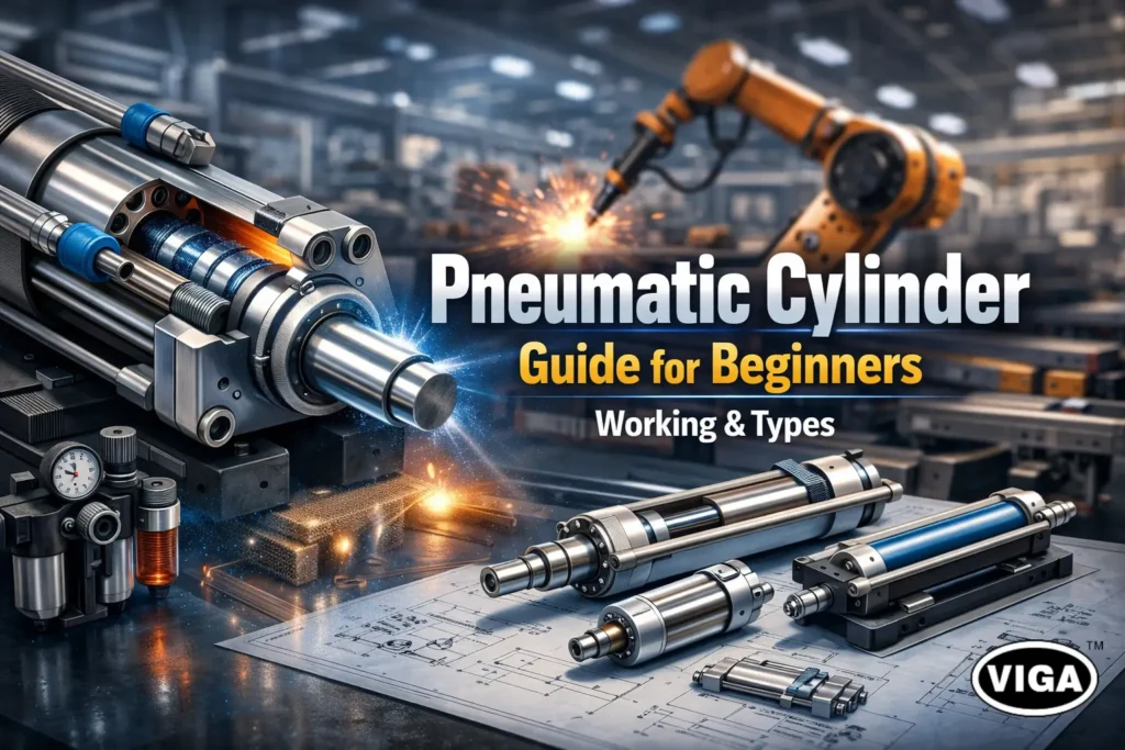
Pneumatic Cylinder Guide for Beginners | Working & Types

They Move Everything — A Beginner’s Guide to Pneumatic Cylinders That Do All the Work! The Power Behind Industrial Movement Step one foot onto a modern automated factory floor and one machine quickly becomes the star: the humble, hardworking cylinder. They’re absolutely everywhere. Clamping this piece, shoving that item down the line, holding something tight for a weld. If it’s fast and straight-line, chances are a pneumatic cylinder is driving it. The entire principle of reliable industrial automation rests on these precise, powerful, and ridiculously common movements. No matter how clever the electronics or robotics get, at some point, you still need reliable physical force, right? That force is delivered, quietly, efficiently, and cleanly, by the system of air-powered workhorses we’re talking about here. For anyone who’s ever had to spec a new assembly jig or simply diagnose a slow packaging machine, you quickly learn you have to know these cylinders cold. In this guide, we’re going through all of it. We’ll break down the very simple pneumatic cylinder working principle, clear up confusion on component selection, and share some real-world secrets on why air quality affects cylinder life. No more guessing games! What Is a Pneumatic Cylinder? Simply put, it’s the motor for straight-line pushing and pulling. A pneumatic cylinder is the machine element that grabs air pressure from the compressor—that costly utility you run all day—and turns it into clean, controllable physical movement. Forget formal descriptions. Think of it like this: A heavy, rugged steel tube (the cylinder) is completely sealed off. Inside is a strong piston connected to an external rod. You shove high-pressure air into one end, and it instantly forces the rod out the other end. That’s it. It’s an air-powered actuator. In a catalogue, you’ll see the official title of a linear motion actuator, because that rod doesn’t spin; it goes back and forth. You won’t use these for driving conveyors—you’ll use them for things like operating machine safety gates or punching small holes. Any job that requires a single, powerful push or pull stroke is best handled by this kind of pneumatic actuator. They are rugged simplicity. How Pneumatic Cylinders Work The elegant thing about the pneumatic cylinder working principle is that it is a pure demonstration of pressure: when force has nowhere to go but one direction, it goes that direction with all its power. Role of Compressed Air The air comes from your facility’s system, but its path is strictly controlled by valves. That valve directs the high-pressure compressed air actuator energy toward the cylinder’s chambers, effectively deciding where the muscle power is needed at that moment. The moment that high-pressure source is hooked up, the system is primed. Piston and Cylinder Movement The sealed, interior piston is what actually gets the job done inside the casing. It’s sitting in there, essentially separating the volume of the tube into a ‘forward’ side and a ‘back’ side. You want to make the rod go out? You create more pressure on the back side. Conversion of Air Pressure into Linear Force Your directional valve clicks, opening the flow and dumping air at high pressure into the chamber behind the piston head. At the same instant, the front chamber air needs a fast path out—that air is instantly released through a silencer. Since the force against the back of the piston is massive and the force against the front of the piston has gone to zero, the pressure differential creates a swift, continuous linear force until the rod hits the end stop. It’s all about creating and managing a massive imbalance. Fast and dependable every time. Main Components of a Pneumatic Cylinder If you’re expected to maintain these, you need to know which parts are disposable and which parts are critical structure. When checking component specifications, pay close attention to the structural aspects. Cylinder Barrel: It’s the fixed body of the tool. Key design point: the inner surface must be flawless, with zero nicks or rust spots, or your seals won’t last ten minutes. Piston and Piston Rod: The piston is the round head that air pushes. The piston rod is the thick, hardened steel bar that actually extends out into the machinery. A bent rod is an almost instantaneous trip to the scrapyard. End Caps (Heads): These are the structural lids that seal the unit shut and provide the necessary Air Ports to feed pressure. They often contain the mounting threads and shock absorbers. Seals and Bearings: These two wear parts define the entire lifespan. The Seals are elastomeric rings that contain the pressure, and the Rod Bearings are the bronze collars that ensure the rod stays straight. Failures in this area mean immediate loss of power. Types of Pneumatic Cylinders Explained Simply Which type you use boils down to how complex the application is—can you use simple return action, or do you need control for both movements? Single-Acting Pneumatic Cylinders This cylinder has only one power stroke: the push (or the pull). It only uses one air line. When you stop supplying air, a pre-installed return spring takes over, shoving the piston back to the home position. Key trade-off: It saves on air consumption, but the piston has to work against that internal spring force, meaning its overall pushing strength is significantly less than the double-acting unit. Simple for tasks like quick door openings. Double-Acting Pneumatic Cylinders This is the machine’s choice for precision control. A double-acting pneumatic cylinder has power on both ends: air to push out, and separate air line control to pull it back in. Key advantage: Provides maximum force for the cylinder’s size in both directions. Essential for pneumatic motion control applications that require high force throughout the entire stroke length. It does, however, use twice the volume of compressed air. Rodless Pneumatic Cylinders Imagine trying to stabilize a long piston rod when moving a 400-pound load over a 15-foot distance. Impossible. The rodless pneumatic cylinders solved this problem by sealing the air in the barrel but letting an external sliding saddle do the heavy movement along a guide. They save tremendous space and are vital in large gantry and positioning systems. Where Pneumatic Cylinders Are Used These units are the quintessential industrial automation components because their usage is so widespread and reliable. Manufacturing and Assembly Lines: Their high

Why Your Air Compressor Needs the Right Air Filter
Blog

Why Your Air Compressor Needs the Right Air Filter

Let’s start with a foundational, critical fact that is often missed in the chaos of the shop floor: Your machinery lives or dies by the quality of its air. Think about your own lungs—they require clean, filtered air to survive and function optimally. Now, translate that necessity to your complex industrial system. For the industrial world, the compressed air supply is an omnipresent utility, the literal engine behind countless operations. The crucial comparison here is immediate and profound: If humans can’t survive polluted air, neither can your compressor. We see the damage all the time: that high-value CNC machine whose valves are sticky, that sudden spike in abrasive dust clogging a critical high-precision solenoid. This is the handiwork of dirty compressed air, the subtle saboteur lurking in the lines. The only thing standing between microscopic, corrosive filth and your most expensive equipment is the unsung hero—the Air Compressor Filter. Take, for instance, a large factory where metal filings and water vapour are drawn in every second. When those impurities meet high pressure and move into the pneumatic valves, it inevitably results in damaging wear and unplanned downtime. This happens because why compressor needs air filter isn’t simply about capturing dirt—it’s about preserving a controlled operating environment. Neglecting a robust compressor air filtration strategy is choosing risk over reliability. In this guide, we cut through the confusion and explain exactly why and how your filtration strategy determines your company’s uptime and financial health. A perfectly functioning, long-lasting system must deliver demonstrably clean compressed air—that much is certain. Why Clean Air Matters in Compression Systems We rely on compressed air so fundamentally that we often stop thinking about what it actually is. It’s often referred to as the “industrial oxygen”, indispensable power that drives robotic actuators, sorting lines, and material handling systems. Yet, air that enters your system is rarely pure; it’s loaded with everything from local street dust to pollen, and worst of all, latent moisture. Here’s the danger: as the air volume is crushed from atmospheric pressure to the required system pressure, those atmospheric contaminants become intensely concentrated. The parts per million of moisture and dust is multiplied, effectively turning a mild atmospheric irritant into a corrosive, damaging cocktail inside your equipment. The real cost comes in the hidden breakdown that results in the costly effects of dirty compressed air. You get: Rusting components as water condenses downstream. Clogs formed by fine particulates and condensed oil aerosols. Wasted energy fighting back-pressure and flow restriction. An operation’s credibility and bottom line hang in the balance, requiring an immediate elevation of technical due diligence, what experts call a solid compressor air filtration program. What Exactly Is an Air Compressor Filter? If your compressor is the engine, the Air Compressor Filter is the specialized guardian standing between the volatile outside environment and your critical tools. It is, perhaps, most easily visualized as a super-industrialized version of your kitchen’s coffee filter, tasked with far more complex particle removal and chemical capture. What is the main role of an air compressor filter? Its three-fold primary purpose is: capturing solids, facilitating moisture separation, and adsorbing oil and solvent vapors. It isn’t merely a physical screen, but an engineered separator. In the physical setup of a Clean Compressed Air System, you don’t typically see just one filter; you see a ‘filter train.’ Filters are intentionally placed downstream from the compressor’s receiver tank. Why there? Because the compressed air needs time to cool down. As it cools, the hot vapour quickly turns back into liquid water (condensate and aerosols). It is far more efficient for the modern Air Compressor Filter to deal with liquid droplets and sticky residues than try to scrub pure gas. That staged, strategic installation is fundamental to running a professional Compressed Air System. How Dirty Air Damages Your Compressor & Pneumatic Tools When air contamination breaks through your primary defenses, the process moves instantly from productive function to guaranteed destruction. This rapid breakdown demonstrates why paying for clean air is simply smarter than paying for replacement parts. The problem boils down to abrasive damage and systemic clogs, both leading to catastrophic component stress. Internal Component Seizure and the Sandpaper Effect: Fine dust and dirt aren’t filtered, but they’re accelerated. They create a “sandpaper effect” inside air-driven components, increasing friction on critical seals, pistons, and rotors. The result? Premature wear, reduced stroke consistency, and seals that start leaking precious pressure. This mechanical damage confirms why clean air is so vital—otherwise, it’s instant Compressor Damage. The Ruin of Seals and O-Rings: High heat and consistent exposure to contaminated water condensate drastically accelerates the degradation of rubber and plastic seals. This failure manifests as countless, expensive leaks throughout your system. Once air is leaking, your system’s required run time increases exponentially to compensate, undermining overall compressor efficiency. Rapid System Failure and Clogging: Perhaps the most frustrating immediate Effects of Dirty Compressed Air is system stalling. Oil aerosols that condense in cool air lines combine with dust to create sticky sludge. This thick grime jams and obstructs the fine tolerance control components within critical spool and pilot valves, leading to near-immediate pneumatic system failure that requires hours of troubleshooting and manual valve teardown. Negating Tool Reliability: Let’s be honest: if you want to know how air filters protect pneumatic tools, look at the replacement bills. Unfiltered, dirty air voids warranties because manufacturers know that moisture and grime erode the finely tuned lubrication within an air tool, causing motors to bind up and bearings to rust prematurely, confirming that using Dirty Compressed Air on precision tools is financially suicidal. Types of Air Compressor Filters Any expert will tell you: if your filtration system uses a single element to do a complex, multi-layered job, you’ve set yourself up for early failure. Filtration systems rely on a tailored, step-by-step approach. Types of air compressor filters must be selected based on the specific type of impurity you are trying to mitigate, showcasing a depth of professional Expertise. Filter Type Primary Action / Location Contaminant Target Rationale for Use General Particulate First stage (bulk pre-filter). Large solid particle removal (dust, rust, dirt). Protects the more delicate, high-value filters downstream. Coalescing (General Duty) Middle stage. Oil aerosols, condensed water, and fine solids (up

FRL Unit
Blog

What an FRL Unit Does and Why Your Pneumatic System Needs It

Your Pneumatic System Is Useless Without This — Know What an FRL Unit Does! Your pneumatic system can fail in seconds without an FRL unit. It may sound overly dramatic, but any seasoned maintenance engineer will confirm it’s a sobering fact. It’s like pouring low-grade, sandy fuel into a precision engine. You know the engine won’t last long, right? The same basic rule applies in industrial automation: quality power is necessary for system longevity. I’ve personally seen expensive machinery—a $50,000 piece of equipment—come to an immediate, dead stop. The cause wasn’t a PLC failure or a burnt-out motor. It was a simple, seized-up solenoid valve, crippled by condensation-induced rust because its air supply lacked proper preparation. The lost production time on that factory floor far exceeded the cost of a hundred FRL units combined. This is exactly why the FRL Unit (Filter, Regulator, Lubricator) is universally regarded as the critical component in air preparation. Without this essential trio, the very source of your factory’s power—compressed air—shifts from an energy medium to a damaging contaminant. What Exactly Is an FRL Unit? If you’re new to the topic and asking, “What is an FRL unit?” here is the most straightforward explanation you’ll find: FRL stands for Filter, Regulator, and Lubricator. It’s an integrated, three-part system installed in your compressed air line, positioned directly upstream of the machinery it serves. Its fundamental mission is three-fold: to scrub the air clean, to manage the pressure, and, often, to condition the air with a fine oil mist. Raw, untreated compressed air from a large industrial compressor is surprisingly harsh. It’s hot, full of condensed water vapor, microscopic grit, and minute particles of burnt compressor oil. If this “dirty air” hits delicate seals and internals, it’s highly corrosive and acts like a steady stream of liquid sandpaper. The complete Air Filter Regulator Lubricator combination cleans this corrosive medium, turning it into a stable, conditioned power source suitable for precision tools and sensitive industrial machinery. Why Every Pneumatic System Is Useless Without an FRL Unit You might look at the cost of an FRL and decide to “value engineer” it out of the setup. This choice is, unfortunately, a guarantee of catastrophic, non-preventable system failure. Importance of FRL Unit in Pneumatic Safety and Longevity: Moisture Damage: Condensation within a compressor’s storage tank creates massive amounts of water. Without the Filter, this water rushes downstream, stripping away the necessary factory grease inside tools and cylinders and causing instant rusting of critical metal components. Pressure Inconsistencies: The demand on a compressor constantly fluctuates. A tool designed for a steady 90 PSI can be suddenly blasted with 120 PSI or more from the line. The Regulator acts as a crucial barrier, preventing this kind of shock and seal blowout. Increased Tool Wear: High-speed air motors require constant, fresh lubrication. Without the Lubricator component supplying a fine mist, internal metal-on-metal friction increases exponentially, leading to bearing failure, component seizure, and premature burnout. Skyrocketing Maintenance Costs: Understanding how an FRL unit protects pneumatic equipment is simple math. A good unit costs anywhere from $50 to $200. An unpreventable production stoppage caused by a seized cylinder on your line can cost upwards of $5,000 per hour in lost revenue. From the point of view of safe, reliable engineering, running any piece of machinery off of raw air is negligent. The installation of an Industrial FRL Unit is a core component of preventative maintenance and a crucial insurance policy. Deep Dive: How Each Component Works To truly appreciate the FRL Unit Working Principle, you need to understand the physics governing the three distinct components. They work in tandem but perform separate, non-negotiable tasks. ✔ Filter (F) — The First Line of Defense Incoming air rushes into the filter bowl. Special vanes (deflector plates) force the air into a fast, downward spiral, creating a powerful cyclone (centrifugal force). This action flings heavier, larger contaminants (like water slugs and heavy dust) against the sides of the bowl where gravity allows them to drain. The now partially-clean air passes through a finely porous sintered element (typically 5 to 40 microns) to trap any remaining, fine dust particles. Primary Job: Aggressive debris and moisture removal in air lines. ✔ Regulator (R) — The Control Center Once cleaned, the air moves to the regulator section. Inside, a flexible diaphragm balances against a mechanical spring. You “set” the required pressure (e.g., 6 Bar) using the large knob. This control maintains a rock-steady output pressure. If the downstream pressure unexpectedly increases, a relief feature “bleeds off” the excess air to maintain your setpoint. Primary Job: Precise Air pressure regulation. This creates consistent torque, clamping force, and operating speed for your final equipment. ✔ Lubricator (L) — The Life Extender Finally, the conditioned air enters the lubricator bowl. It utilizes the fundamental Venturi effect: air accelerates quickly over a tiny opening, creating a localized vacuum. This negative pressure then sucks (or “draws”) specialized oil from the reservoir and instantly atomizes it into a fine, highly stable mist. This oil mist is carried to and deposits a necessary protective film on every valve, cylinder, and high-speed moving part. Primary Job: Critically reducing friction and preventing internal component corrosion. Benefits of Using an FRL Unit in Industrial Pneumatic Systems Investing in a high-quality Pneumatic FRL System delivers a powerful return on investment (ROI) that you can immediately observe on your shop floor. Extended Equipment Lifespan: Equipment that receives clean, consistently-pressurized, and lubricated air routinely lasts three to five times longer than those fed with raw air. Reduced Downtime: You drastically cut the risk of emergency failures. Fewer unplanned stops means your manufacturing processes keep moving predictably. Energy Efficiency: A regulated pressure saves energy. Why waste expensive compressed air feeding a line at 110 PSI when the tool you’re powering only needs 80 PSI? The regulator stops this waste. Enhanced Safety: Equipment pneumatic tools safety is based on predictable force. An FRL mitigates the significant risk of pressure spikes that can lead to catastrophic component failure, hose whipping, or a dangerous breakdown. Improved Air Quality: Protecting expensive downstream components (like proportional valves) from upstream particulate contamination. Signs Your Industry Needs an FRL Unit Right Now If you are seeing any of these

Air Lubricators
Blog

Why Air Lubricators Are Essential for Pneumatic Machine Life

The Secret to Longer Pneumatic Life — Why Air Lubricators Matter More Than You Think! Dry Air is a Destroyer When you are deeply involved in manufacturing or industrial maintenance, your most overlooked source of catastrophic failure is the very thing you use for power: dry compressed air. I can tell you from decades of experience, your Air Lubricator is the single best, simplest piece of defensive engineering you can install. It’s what protects your large investments from an incredibly simple flaw. Let’s face an unavoidable truth: dry air destroys pneumatics faster than anything else. You might have budgeted tens of thousands for high-end compressors and meticulously regulated valves, but once you start running air—filtered, moisture-stripped air—through any rapidly moving pneumatic part, you’ve created an environment of severe, accelerated self-destruction. The reason is a total absence of a separating layer. Think about a critical process stopping—it’s usually not a monumental failure; it’s a minor thing: A High value precision valve that, after three months, just can’t snap its internal spool to the correct position. That phenomenon, the dreaded sticking valve, is a textbook example of component destruction through zero pneumatic tool lubrication. What you are hearing and seeing is uncontrolled metal or plastic rubbing against metal under extreme, repetitive stress. Your focus should be on the small investment that delivers huge operational freedom. The lubricator isn’t an option; it’s an absolute necessity. It is the crucial guardian that ensures genuine tool life enhancement, converting an abrasive medium into a seamless vehicle for internal protection. Ignoring this basic truth leads directly to unpredictable and often catastrophic failure cycles.  What Is an Air Lubricator? Before you can appreciate the complex mechanical protection it provides, we must simplify its purpose. So, for someone completely new to this: A Pneumatic Air Lubricator is basically an on-demand, precise dispensing machine for lubricant that gets carried along inside your existing pipe network. It automatically transforms a specialized, low-viscosity oil into a cloud and injects it into the compressed air flow before it hits the point of work. The system function, or the core Air Lubricator Function, is this: ensuring that critical, dynamic parts that are otherwise impossible to manually grease receive an uninterrupted film of protection. That layer is the barrier that prevents the surfaces of your valves, spools, and cylinder rods from ever making contact with each other. You usually see it in the field as the final component in what’s called the FRL Lubricator Unit (Filter, Regulator, Lubricator). If the filter cleans the air and the regulator stabilizes the pressure, the lubricator handles the final and perhaps most important piece of conditioning: adding a controlled dose of mist lubrication. It has to be the last component because putting oil upstream would destroy filters and cause control problems in the regulator’s pressure mechanism. Its careful placement guarantees that every cubic foot of air leaves ready to work and ready to protect its equipment. Why Pneumatic Components Need Lubrication Any experienced maintenance technician knows the real enemy is friction, not just dust. To be a true expert in pneumatics is to grasp the engineering logic of why friction is a system killer and why lubrication is an immediate necessity. This goes to the heart of the Importance of air lubricators. Real-World Mechanics and the Path to Wear We rely on incredibly fast-moving components that depend entirely on close tolerances and intact seals. Without a proper lubricating film, these dynamics work to tear themselves apart. Friction-Induced Heat is a Seal Killer: Actuators run at high cycles per minute. In dry conditions, friction rapidly generates substantial heat right where the piston seals meet the cylinder wall. What happens next is irreversible: That heat hardens the polymer or rubber seals, turning them brittle and compromising their flexibility. Once the seal loses its supple nature, it starts cracking. Pneumatic Wear: Once a seal is brittle or compromised by high heat, its integrity is lost. This results in leakage and the abrasive scouring of the cylinder’s internal surface. The Pneumatic Wear then accelerates—microscopic scores and imperfections develop, allowing more friction, more heat, and more wear. The Stiction Nightmare: This is the most visible operational fail. When a valve’s internal spool requires more pressure (more energy) to begin sliding than to continue sliding, it “sticks.” This is usually due to microscopic dry air damage and an utterly depleted seal layer. This translates directly to an instant hit on production efficiency and system reliability. Essentially, when a lubricator is skipped, you trade preventative wear prevention for an immediate and guaranteed acceleration of your components’ age, resulting in an unjustifiable reduced lifespan across your system.  How Air Lubricators Work How does a single drop of oil, released under control, manage to travel 50 feet and perfectly coat an O-ring inside a manifold? It’s not magic; it’s an elegant use of air dynamics. The technology’s effectiveness lies in its core component, the sophisticated oil mist generator. The oil must be broken down to the sub-micron level so that it remains suspended in the high-speed air. The Sight-Feed Control: Oil is stored in the reservoir, but it’s released with meticulous precision. A needle valve or metering screw controls the lubricator oil flow, creating the slow, steady drip rate you observe in the sight-feed glass. This flow is constrained, ensuring you are not flooding the system but rationing the dose perfectly. The Venturi Principle (Generating Vacuum): The incoming compressed air passes through an internal restriction—the Venturi throat. By decreasing the volume for the air flow, you drastically increase the air velocity, which—due to basic physics—causes a rapid drop in local static pressure. That drop creates a crucial, local vacuum. Oil Uptake and Atomization: This generated vacuum then acts like a miniature, precise pump, drawing the precisely metered drop of oil up from the reservoir. When the single oil droplet meets the extremely high-velocity air in the restriction, it’s shattered into a fine aerosolized suspension—the perfect lubricating mist lubrication. Distribution: Air as the Carrier: Now, this is key. The minute size of the oil particles ensures they do not fall out of the airstream immediately (like rain). Instead, the high-pressure air acts as a perfect delivery vehicle, ensuring every complex, tiny channel, O-ring groove, and valve seat

Air Pressure Regulators
Blog

How Air Pressure Regulators Prevent Pressure Drops

The Air Regulator Difference: Achieving Rock-Solid Operational Stability Air Pressure Regulators are the most undervalued assets in the vast majority of industrial setups, yet they prevent production disasters every single minute of every working day. You know that gnawing anxiety—that tiny, cold fear that hits when a high-speed assembly sequence on your line hesitates, stutters, or momentarily loses power. We’ve all seen the resulting disaster: a part is misaligned, a torque wrench underperforms, or a paint finish suddenly appears patchy. The cause, far too often, is traced back not to a faulty machine, but to the inherently unpredictable nature of its energy source. Let’s be candid. You spend a fortune on a high-end air compressor, capable of delivering a beastly 175 PSI. Logically, the air should be perfect at the workhead, right? Wrong. The moment a compressor cycles, a distant machine engages, or a major line manifold is accessed, that output pressure violently shifts. Imagine running an automated screw feeder that requires precisely 75 PSI for repeatable performance. Without consistent control, an air spike might blow a seal, while a sudden pressure drop might cause an unacceptable half-turn on a crucial fastener. This true industrial scenario illustrates why we constantly fight the specter of instability, underscoring the massive importance of an air pressure regulator for continuous output quality. The truth is, reliable operation hinges entirely on controlling the very air you feed your machines. What Causes Pressure Drops in Pneumatic Systems? You cannot fix chaos until you know its root cause. If your machines are consistently battling chronic performance problems, a significant pressure drop in pneumatic systems is the likeliest culprit. You might be paying a premium for compressed air, but your machinery is receiving volatile fluctuations, contributing to significant Pneumatic Pressure Loss. We have to drill down into the non-negotiable answers to Causes of Pressure Drops : The Turbulent Compressor Source: I know you paid for a steady supply, but the fact is, the tank is always refilling, starting, and stopping. This natural fluctuation means the high-side supply line pressure constantly varies by 10 to 20 PSI—it’s never truly constant. Without an Air regulator for compressor output, that erratic feed immediately introduces chaotic pressure spikes and falls across your entire compressed air system. Simultaneous Demand Overload (Systemic Starvation): The common issue of multiple tools or actuators activating concurrently—an air blast here, a major clamp there. These demands instantly create a brief but substantial localized vacuum, starving the immediate local area of volume (CFM) and dramatically dropping the pressure. This peak flow deficiency is why many Why pressure drops happen in air lines incidents occur only during maximum production speed. Chronic and Undiscovered Line Leakage: This is the invisible money pit. You’d be surprised how much pressure—and, thus, money—is hemorrhaging through tiny, neglected seals or slightly loose hose clamps across a large facility. That persistent, collective hiss forces your compressor to run longer and harder, which directly and consistently degrades the baseline stable air pressure available to your devices. Air Quality and Pipeline Resistance: If you aren’t diligently maintaining your upstream dryer and filter, moisture and contaminants collect inside the piping. Over time, that buildup reduces the actual flow diameter, creating frictional resistance that mimics a chronic bottleneck. This hidden choke point translates into a measurable loss of performance right where the actuator requires its full push force. Design Flaws: The Curse of Undersizing: A mistake made years ago by a systems designer: installing piping that is simply too small for today’s demand load. While you can send enough pressure, the piping can’t pass the volume without creating significant friction, resulting in an inherent pressure-loss defect built into the structural DNA of your pneumatic system efficiency setup. What Is an Air Pressure Regulator? Let’s be incredibly clear about the function. The Air Pressure Regulator acts as a dedicated pressure-reducing and stabilizing mechanism. Its purpose is entirely focused: it converts the unpredictable, high input pressure from the supply source into the precise, much lower set-point of stable air pressure required by the tool. And crucially, it holds that output number static, almost without exception. The Crucial Last Step Positioning is key for success. The regulator isn’t installed next to the huge main tank. Instead, you’ll find it strategically located immediately before the end-use device, usually integrated with the final filtration—often less than five feet from the pneumatic cylinder it controls. This point-of-use proximity ensures highly localized downstream pressure control , meaning its mechanical action accounts for the last moments of turbulence in the line, securing pressure consistency exactly where performance is judged. Know the Difference: Regulator vs. Relief Valve An expert distinction must be made here, as relying on one to do the job of the other is a frequent industrial mistake that risks costly damage: The Air Pressure Regulator (The Governor): This device performs the active work of control and reduction. Its mandate is operational—it makes sure the output pressure never exceeds the set-point during normal use. The Safety Relief Valve (The Safety Fuse): This component is designed to remain completely passive until a catastrophic event occurs—it only activates to dump pressure overboard if the entire system unintentionally over-pressurizes far above the regulator’s cap. Its sole job is the final defense against extreme failure and overpressure damage from structural rupture. The regulator is a full-time operator; the relief valve is merely the ultimate, last-second safety back-up. How Air Regulators Keep Air Pressure Stable How exactly does this clever arrangement of components achieve such unerring stability? The mechanical truth of how air regulators work is based entirely on the principle of mechanical counter-balance. Every reliable regulator utilizes its core components—the adjustable spring, the sensitive diaphragm (or piston), and the shut-off valve—in a perpetual negotiation. The moment you adjust the knob, this internal process begins: Setting the Control Standard (Downward Force): By turning the adjustment knob, you physically load the main internal spring. The resultant tension creates a measurable, downward mechanical force on the system’s flexible diaphragm or sensing piston. This is your commanded stable air pressure target (e.g., 90 PSI). Measuring the Operational Reality (Upward Force): On the opposite side of the diaphragm, a separate sensing line continuously channels the regulated output air pressure (the downstream pressure). This air creates a corresponding upward pressure force against the diaphragm, directly opposing the force of the spring. The Sweet Spot

Top 5 Factors Pressure Gauge Selection Guide for Industry Needs
Blog

Top 5 Factors: Pressure Gauge Selection Guide for Industry Needs

Top 5 Factors to Consider Before Selecting a Pressure Gauge for Your Industry Accurate pressure measurement is more than just a metric; it is the cornerstone of safety, quality control, and operational efficiency across every major industry. In critical environments, from refining crude oil to manufacturing pharmaceuticals, a malfunctioning or improperly chosen pressure gauge can lead to disastrous equipment failure, significant downtime, or even hazardous safety incidents. When selecting instrumentation for industrial process monitoring, choosing a pressure gauge often seems straightforward—but it shouldn’t be a hurried, box-ticking exercise. The nuances of your specific application demand a careful, methodical approach. This detailed Industrial Pressure Gauge Selection Guide outlines the top five factors that must influence your decision, ensuring you choose an instrument that provides reliability and precision for years to come. What Is Pressure Gauge Selection & Why It Matters Pressure gauge selection is the strategic process of evaluating a system’s requirements (media type, pressure range, environment) against a gauge’s specifications (accuracy, material, type) to achieve optimal performance, safety, and longevity. We commonly encounter pressure gauges in various sectors: regulating gas lines in chemical manufacturing, monitoring sterilization chambers in pharma, measuring wellhead pressure in oil & gas, or maintaining quality control in the food and beverage industry. A wrong selection can have severe consequences. For example, selecting a gauge with poor pressure gauge material compatibility for an abrasive chemical could lead to rapid internal corrosion, causing media leaks, costly equipment downtime, and, potentially, equipment rupture. Learning how to choose a pressure gauge correctly, therefore, is essential to protect assets and personnel. The Top 5 Critical Factors Factor 1: Pressure Range & Measurement Accuracy This is perhaps the most fundamental factor in pressure gauge selection criteria. Misjudging the operational pressure range can destroy the gauge rapidly or render its readings meaningless. The Golden Rule for Range Selection: The normal working pressure of your system should fall between 40% and 75% of the full-scale range (FSR) of the selected gauge. Example: If your typical operating pressure is 400 psi, your chosen gauge should have an FSR of approximately 600 psi to 1000 psi. Why 75% is the recommended limit: Constantly operating a gauge above 75% FSR significantly reduces the lifespan and negatively impacts its calibration due to over-stressing internal components. Measurement Accuracy: The accuracy class determines how closely the reading represents the true pressure. For standard industrial use, an accuracy class of ±1%±1%  is typical. However, for critical monitoring and calibration standards, ±0.5%±0.5%  or even ±0.25%±0.25%  accuracy is crucial. Higher accuracy translates to better control and safety, justifying a higher investment.  Factor 2: Process Media & Material Compatibility The medium the gauge is monitoring (the process fluid or gas) is a major determinant of material choice. This step is about preventing premature gauge failure and protecting against contamination. Process Medium Common Compatibility Issues Recommended Materials Water, Air, Oil Standard conditions Brass or Bronze Mild Corrosives Chemical corrosion Stainless Steel 304 (SS 304) Highly Corrosives (Acids, Ammonia) Pitting, rapid deterioration Stainless Steel 316L (SS 316L) or Monel/Hastelloy Slurries, Viscous Media Clogging, buildup Diaphragm Seals with non-metallic filling Failure to ensure gauge material compatibility, especially in chemical and high-purity environments, can be dangerous and extremely costly. Selecting the best pressure gauge for industrial use means first checking the fluid characteristics. Factor 3: Operating Environment & Application Type The external conditions surrounding the gauge have a profound impact on its reliability. Neglecting environmental stressors often leads to premature failure, regardless of how accurate the gauge itself is.  Vibration and Pulsation: Machinery vibration (e.g., near compressors or pumps) can damage the gauge movement (gear train and pointer). For such environments, selecting a liquid-filled pressure gauge (often filled with glycerine or silicone) is essential. The damping fluid stabilizes the pointer, reduces wear on internal gears, and extends the gauge’s lifespan. Temperature: Both high ambient temperatures and high process media temperatures must be addressed. High process temperatures require the use of accessories like cooling siphons (for steam) or chemical seals to isolate the gauge from the heat, ensuring the internal components remain within their operational temperature limit. Factor 4: Gauge Type & Mounting Configuration Industrial pressure monitoring applications require a variety of gauge types, each suited for a different measurement principle and fluid characteristic. Bourdon Tube: Most common, reliable for general process applications. Diaphragm/Capsule: Best for low pressures (Draft pressure) and protecting the sensor from clogging fluids (slurries). Digital Gauges: Offer high accuracy, readability, and integrated features like data logging and analog output, making them invaluable for precise monitoring and compliance in advanced facilities. Beyond the type, correctly choosing the pressure gauge size, range, and connection type (e.g., NPT, BSP) and ensuring a correct mounting configuration (panel, surface, or direct line) is key to proper installation and viewing accessibility. Factor 5: Calibration, Maintenance & Reliability A gauge is only reliable if its readings can be trusted. Pressure gauge calibration is not just an expense; it’s an insurance policy. Calibration confirms the accuracy of the device against known standards (like ISO/ASME) and is crucial for maintaining compliance and product quality. [Keywords: Pressure Gauge Calibration, Pressure Gauge Reliability] Industry best practice recommends establishing a recommended calibration interval based on the gauge’s environment, accuracy class, and criticality to the process, usually every 6 to 12 months. Routine checks and preventive maintenance, such as checking for external leaks and ensuring the pointer moves freely, will prevent catastrophic system failures and uphold long-term reliability. Bonus Tip: Safety Standards & Certifications When it comes to industrial pressure gauge safety, verify that your gauge complies with established national and international standards such as ASME B40.100 (U.S.) or EN 837 (European). These certifications ensure the instrument meets rigorous safety design requirements, including burst pressure and housing integrity. Always request supplier documentation to confirm traceability and manufacturing quality. [Keywords: Pressure Gauge Standards, Industrial Pressure Gauge Safety] Common Mistakes to Avoid While Selecting a Pressure Gauge A clear path to effective pressure measurement often begins with identifying potential pitfalls. The following common mistakes while choosing a pressure gauge should be actively avoided: Selecting

Industrial Pressure Gauges Comparing Triclover, Capsule, Homogeniser & Test Gauges
Blog

Industrial Pressure Gauges: Triclover, Capsule, Homogeniser Comparison

Industrial Pressure Gauges: Comparing Triclover, Capsule, Homogeniser & Test Gauges Within the complex operational landscapes of manufacturing, processing, and industrial facilities, the capacity to precisely monitor and control system dynamics represents the core of operational excellence. Process stability and safety are inherently dependent on the instrumentation chosen, particularly the measurement of pressure. As such, the selection of the correct measuring device demands careful consideration of not only range and media but also the device’s design intended purpose. Industrial Pressure Gauges serve as primary safety indicators and critical control loop elements. The fidelity of these instruments dictates product quality, adherence to strict processing recipes, and ultimately, personnel safety. Failure to select the proper gauge can lead to measurement drift, premature component fatigue, and devastating failures in high-risk environments. This necessity explains Why accuracy and calibration matter in industrial applications. Ensuring the gauge’s reading aligns precisely with actual process conditions provides the foundation for safe, compliant, and cost-effective operations. Understanding the specific mechanics and advantages of highly specialized instruments allows industry professionals to make informed procurement and maintenance decisions. This analysis offers a detailed comparative review of the hygienic Triclover Pressure Gauge, the sensitive Capsule Pressure Gauge, the high-endurance Homogeniser Pressure Gauge, and the critical Test Gauge for Calibration. An exploration of these distinct devices illuminates the sheer variety of Types of Industrial Pressure Gauges available to meet any industrial requirement. What Are Industrial Pressure Gauges? Industrial Pressure Gauges are indispensable devices designed to convert fluid force exerted on a sensing element into a readable value, typically displayed on a dial scale or digitally. The classical working principle—the mechanical gauge—revolves primarily around the utilization of the Bourdon tube. This C-shaped, helical, or spiral tube, typically forged from bronze or stainless steel, is flattened into an elliptical cross-section and closed at the tip. When process pressure is applied, the tube attempts to return to a circular cross-section, causing the free end to straighten. This minute displacement is magnified by a gear and pinion mechanism, ultimately driving the pointer around a calibrated dial. The application of these instruments transcends simple observation. Their continuous readings are vital for the efficient and safe execution of various industrial activities across the spectrum, from fine chemical handling and precision food manufacturing to controlling the energy flow in large-scale chemical plants. A well-maintained and calibrated gauge serves as the physical link to established safety limits and Pressure measurement standards. Furthermore, in industries facing high vibration or pressure pulsation, appropriate modifications, such as liquid-filled casings, are utilized to protect the sensitive internal mechanisms and enhance pointer stability, thereby guaranteeing reliable readings even under dynamic operational duress. Proper knowledge of Industrial Pressure Gauge Calibration ensures regulatory compliance and optimal process control integrity. Triclover Pressure Gauge The Triclover Pressure Gauge distinguishes itself not primarily by its internal sensing mechanism, but by its distinct connection design. Also referred to by its common industry name, the Triclamp, this sterile coupling facilitates a smooth, crevice-free junction with the process line. This feature is the hallmark of its widespread utility in sectors requiring exceptional levels of sanitary design. Its function is inherently linked to hygienic applications. When a standard threaded gauge or an exposed diaphragm assembly is utilized, media, contaminants, or microscopic biological materials can become lodged in the tiny thread gaps or sharp corners, making cleaning-in-place (CIP) or sterilization-in-place (SIP) ineffective. The use of a smooth, gasketed seal, clamped by the easy-release Triclover ferrule system, solves this crucial industry challenge. The construction materials invariably consist of high-grade, often electro-polished, Stainless Steel Pressure Gauges (typically 316L). This resistance to aggressive media and rigorous cleaning chemicals is not merely an advantage; it is a fundamental requirement in regulated environments like dairy, pharma, and food/beverage processing. Advantages central to this design include superior process integration due to easy to clean capabilities, guaranteed reliable sealing through the robust gasket compression, and its inherent corrosion-resistant nature, which prolongs the instrument’s operational life dramatically while maintaining strict sanitary validation. For applications where process cleanliness directly affects consumer safety, the Triclover design offers unparalleled assurance. Capsule Pressure Gauge When applications involve the measurement of exceptionally low pressure—differential pressure, draft pressure, or flow in specialized air or gas lines—the traditional Bourdon tube lacks the requisite sensitivity. For such scenarios, the highly sensitive Capsule Pressure Gauge offers the precise solution. The operational principle of this device centers on an enclosed element known as the capsule, which gives the instrument its name. The capsule is created by welding or soldering together two thin, deeply corrugated diaphragms along their perimeter. This assembly creates an enclosed chamber where pressure from the process media is introduced. As pressure is exerted internally, the sensitive corrugated shape allows for a greater displacement and mechanical stroke even at pressures below 1 psi (or 27 inches of water column). This large, yet sensitive, displacement is then transmitted through a movement mechanism, effectively converting a negligible pressure change into a measurable dial movement. The Capsule gauges are particularly ideal for gas measurement and filter monitoring applications where extremely minute pressure variations must be registered reliably. They are frequently deployed in laboratories, pharmaceutical isolators, ventilation and air handling units (HVAC), and cleanroom environments where measuring slight low-pressure measurement variations between different controlled zones is necessary for environmental integrity. The primary benefits include their highly accurate reading across a compressed, low-end scale and their simple construction that minimizes fluid contamination in clean environments. Understanding this instrument’s low-pressure capabilities clarifies the notable difference when making a Pressure Gauge Comparison. Homogeniser Pressure Gauge The Homogeniser Pressure Gauge is purpose-built to survive and perform under the most brutal conditions found in specialized fluid processing—specifically the homogenization process employed in the dairy and beverage industries. Homogenization involves mechanically breaking down particles (like fat globules in milk) into uniformly small sizes by forcing the liquid at high velocity through a very small, restricted opening at immense pressures, often in excess of 5,000 to 10,000 psi. This extreme pressure application introduces several engineering challenges. Not only must the instrument withstand

Test Gauges
Blog

Test Gauges: Precision Tools for Calibration and Accuracy

Test Gauges: Precision Instruments for Calibration & Accuracy Checks In engineering and industrial operations, there’s a saying: “If you can’t measure it correctly, you can’t control it correctly.” No matter how advanced a process is, its success ultimately depends on the accuracy of its measurements. For industries such as pharmaceuticals, oil and gas, chemicals, automotive, and utilities, reliable readings of pressure, temperature, and flow mean the difference between consistent quality and serious system failure. When accuracy is critical, industries turn to one tool above all others: test gauges. These instruments are not everyday operational gauges, but specialized precision devices that act as benchmarks for calibration and verification. They confirm whether working instruments are trustworthy, identify inaccuracies that could lead to costly errors, and establish measurement traceability according to recognized standards. This article examines test gauges in detail. We’ll cover their purpose, different types, applications across industries, technical benefits, compliance with global standards, trends in Indian manufacturing, and practical tips for choosing the right gauge. What Exactly Are Test Gauges? Test gauges are precision measuring instruments designed for one main purpose—calibration and validation. Where standard pressure gauges might give readings with a ±1% or ±2% accuracy, test gauges improve that figure dramatically, often down to ±0.25%, ±0.1%, or even tighter tolerances. A useful way to describe test gauges is to call them “referees”. Just as referees ensure a fair game, test gauges ensure that every working instrument—whether it’s installed on a reactor, a pipeline, or a testing bench—is reading accurately. Whenever discrepancies arise, it’s the test gauge that reveals them. Typical characteristics include: High-resolution scales, often with mirrored surfaces to eliminate parallax errors. Precision pointers for finer readability. Robust designs to minimize long-term drift in measurements. Traceable calibration certificates confirming compliance with ISO/IEC or ASME standards. Categories of Test Gauges Precision Test Gauges These are the finest category of gauges, often used where measurement cannot tolerate the slightest deviation. Typical environments include aerospace engineering, defense equipment testing, high-tech laboratories, and nuclear facilities. For example, in an R&D lab testing rocket engine components, even a tiny pressure mismatch may skew results. Precision test gauges ensure readings remain unquestionably reliable. Calibration Test Gauges As the name suggests, calibration test gauges serve as references in calibration processes. Their role is to recalibrate or verify working gauges used in production and field work. Calibration facilities often link a calibration gauge with pumps, pressure controllers, or deadweight testers to compare readings across a defined range. Accuracy Test Gauges Accuracy test gauges represent a middle ground—they are not laboratory-grade, but they are portable, rugged, and suitable for field applications. Maintenance teams, for example, use them during scheduled shutdowns to spot-check operating gauges across plants. Pressure Test Gauges These are the most widely used. Pressure test gauges validate pressure in mechanical, chemical, and hydraulic systems under real operational conditions. Available in sealed stainless steel, liquid-filled for vibration resistance, or diaphragm-protected configurations, they are indispensable across refineries, chemical plants, water treatment units, automotive hydraulics, and HVAC installations. Applications of Test Gauges Test gauges are universal in scope, spanning across industries and purposes. Industrial Calibration In large-scale industries such as steel manufacturing or petroleum processing, equipment often works under high pressures and extreme temperatures. Instruments installed in these systems gradually drift away from their calibration reference. Test gauges for industrial calibration ensure these deviations are detected and corrected before they compromise production safety or quality. Laboratories Laboratories, particularly in pharmaceuticals, biotechnology, and electronics, depend heavily on measurement accuracy. Test gauges in laboratories verify pressure in sterilizers, containment chambers, and controlled experimental setups. If a lab is conducting a test requiring pressure stability within ±0.2 bar, only a test gauge offers confidence that the values being recorded are accurate. Manufacturing and Quality Assurance Factories rely on test gauges to preserve quality assurance. In automotive plants, brake systems, fuel injectors, and hydraulic testing setups all undergo scrutiny with calibrated test gauges. The outcome ensures vehicles leave assembly lines compliant with safety regulations. Utilities and Energy Power generation is another sector that cannot risk inaccuracies. Whether in a thermal power plant measuring turbine steam pressure or a hydroelectric unit monitoring flow control mechanisms, test gauges maintain the delicate balance between efficiency, performance, and safety. Aerospace and Defense For aircraft manufacturers or defense organizations, measurement tolerances are extremely strict. Precision gauges are used in flight simulators, cabin pressurization tests, missile launch system verifications, and more. A misreading here could have consequences measured not in profits, but in lives. Benefits of Test Gauges A common question from plant managers is: “Why invest in test gauges when we already have operational gauges installed?” The answer becomes clear when considering the benefits. Unmatched Accuracy – With tolerance levels as low as ±0.1%, test gauges are several times more precise than regular gauges. Reliability in Calibration Chains – They form the backbone of calibration by providing a reference traceable to national or international standards. Enhanced Safety – Prevents critical equipment failures by verifying that operational gauges reflect true system conditions. Cost Savings Over Time – Downtime, rejected batches, or safety breaches cost much more than investing in proper test equipment. Compliance Assurance – ISO-certified processes and industries under FDA or BIS regulations all require calibration using traceable reference devices. Adaptability – Suitable for use in cleanrooms, industrial plants, R&D labs, and even outdoor maintenance conditions. Standards Governing Test Gauges The credibility of a test gauge lies not just in its construction but in its compliance with recognized standards: ASME B40.100 (United States): Specifies pressure gauge design and accuracy standards. EN 837 (Europe): Governs bourdon-type gauge design accuracy and safety. ISO/IEC 17025: Defines the requirements labs must meet to use test gauges within a traceable calibration chain. BIS Standards (India): Ensure locally manufactured gauges meet national benchmarks. For global operations, using gauges aligned with these standards ensures universal recognition of calibration results. Test Gauge Manufacturing in India Over the past decade, India has built a strong reputation as a provider of calibration instruments, including test gauges. The growing

Homogeniser Gauges
Blog

Homogeniser Gauges for Dairy & Pharma | High-Pressure Accuracy

Homogeniser Gauges in Dairy & Pharma: Ensuring Accuracy Under High Pressure The delicate homogenization of milk and cream in dairy processing plants and the preparation of pharmaceuticals and other critical liquid medicaments in sterile pharmaceutical laboratories rely on and are a product of homogenization pressure processing. In turn, homogenization pressure processing is a sophisticated, intensive high-pressure transformation. Thus, the milk in our cereal and the life-saving medication on a critical day comes down to the operational performance of the homogeniser gauge. It is the silent sentinel of the gauge, enforcing the pressure vigilant to the demanding metrics of high power, the transcendental quality of every product. To achieve homogenization, it is necessary to force liquid through a very narrow gap, where it is subject to tremendous pressure and partitioning that, in turn, creates a stable emulsion. The pressure applied is enormous and can run up to thousands of pounds per square inch (PSI). In the proportional absence of a monitoring and controlling method that is both accurate and reliable, the homogenization process would face the possibility of product failure, equipment compromise, and safety concerns. In these circumstances, homogeniser pressure gauges (HPGs) serve functions that add value to the situation, and the feedback obtained is instrumental to control and consistency of homogenization in systems where precision is paramount. Homogeniser Gauges: The Unsung Saviors On a more fundamental note, a homogeniser gauge is a type of homogeniser instrument that is different from the rest in that it is designed to withstand the very unique and extreme conditions posed by a homogeniser. Most homogenise gauges are made to withstand extreme pressures, but these are different in that they are made to survive extreme vibration and high levels of pulsating pressure that is accompanied by high levels of hygiene usually needed in the pharmaceutical and dairy industries. What is the purpose of a Homogeniser Pressure Gauge? A Homogeniser Pressure Gauge is designed to indicate and measure the amount of pressure used on a fluid while homogenization is in progress. In order to accomplish this in a clean manner, these gauges are almost always in association with a diaphragm seal. A diaphragm seal is used to protect and separate the internal workings of a gauge from the process media, such as milk, liquid drugs, and other formulations. The pressure goes through the diaphragm into a fillable gauge, then to a filling fluid, which then moves the gauge’s pressure sensing mechanism, which is usually a Bourdon tube, The diaphragm and gauge design is crucial as it prevents the process fluid from getting into the gauge and eliminates the contamination. In addition, these gauges are designed and build to endure the constant and severe pulsations of the homogenizer’s pump, a distinctive mechanism that averts the premature failure of these type gauges. The importance of the Gauge of the High-Pressure Homogenizer. The method of homogenization is critically dependent on the pressure used. The pressure applied is critical when breaking down the fat globules in milk or grinding active pharmaceutical ingredients (APIs) into micro sized particles required for stable product formulation. High pressure in these cases is a necessity. The High Pressure Homogeniser Gauges are constructed for these specific workloads. They can gauge pressures exceeding 1,600 bar (or 15,000 psi) in a number of demanding operating conditions, and in some cases, even higher with phenomenal accuracy. These instruments are constructed with extraordinary engineering durability. These factors include the robust parts of the equipment, for instance the diaphragm and process connection parts requiring minimal maintenance and engineered corrosion resistant. These parts are constructed for extreme pressure and extremely small gaps are used in the designs for maximizing accurate pressure readings. The outer casing is engineered with stainless steel 304 for durability and corrosion resistant for the elements. The importance of Purity and Safety: Benefits of Gauge Sanitary Homogeniser. Hygiene is a critical aspect of food and pharmaceutical manufacturing activities. It is for this reason that Sanitary Homogeniser Gauges have been developed. “Sanitary” or “Hygienic” means design of the instrument does not have features like: joins, threads, and spaces which products can hide, and bacteria can multiply. The mirror polished product contact surfaces can be cleaned easily, either manually or through CIP (clean-in-place) systems, because of the absence of ports and dead ends in the system. The apex of the sanitary design is the diaphragm seal which guarantees the safety of the delicate mechanics of the gauge while also avoiding any contamination. The whole assembly is compliant with the stringent of industry regulations like the 3-A Sanitary Standards in the U.S which certify that the equipment is designed and fabricated for easy cleaning and effective inspection. The positive consequences of investing in a high quality and durable gauge homogeniser is felt in various aspects ranging from the product, and operational safety. Enhanced Product Quality and Consistency  In most cases, the more delicate the process, the more difficult and complicated it becomes, and in the case of dairy, the delicate process which border directly with the complicated, and with the most effort and care, maintain the size of each and every fat globule in homogenous milk to the size of a small pinhead. This practice, of course, enables the eater the most efficient and stable experience. quivalently, in the case of pharma products, each granule of the tablet, relative to the correct bioavailability and dosage needed, must also be homogeneous for effectiveness insufficiency. Operational Productivity and Improvement  In the scenario of apparatus, equipment, and other valuable partially finished and finished products, the equipment of, with, and undergoing over pressurization is regulated and controlled with much more certainty, which ultimately helps the people working with it. Rather, it helps them avoid and escape dangerous situations which could put them in a perilous position. Besides, the people working the equipment in the situation of the pour for Liquid with other homogeneous liquid, the people working the equipment which the pour for Liquid happens, it is pourerably much more efficient and effective with an

Capsule Gauges
Blog

Capsule Gauges: Professional Low-Pressure Measurement Solutions

When precise low-pressure measurements are required, capsule gauges are the most reliable option. Standard gauge technology often fails below 1 bar (roughly 15 PSIG) because most common designs are optimized for higher pressures. Bourdon tubes, for example, suffer diminishing accuracy at the low end of their range. Their ability to track rapid changes declines, hysteresis errors increase, and parallax errors exacerbate the disparity between the pointer and actual pressure. When the low side of their characteristic curve coincides with the pressure application of interest, the measurement becomes irrelevant and engineers are effectively measuring noise instead of the signal.  This accuracy shortfall is not an abstract nuisance; it translates to significant risks and inefficiencies in critical applications. Low-pressure monitoring is the unsung backbone of performance assurance in complex HVAC system controls, leak testing of gas distribution lines, and the maintenance of cleanrooms in pharmaceutical manufacturing, among many other processes. Compliance with regulatory and internal audits, safety of personnel, and the integrity of manufactured products all rely on reliable low-pressure data. When the instrument fails to provide that data, the alternative is often unsafe guessing, which in turn leads to costly and potentially damaging corrective actions.  This is where capsule pressure gauges assert their distinct value. They are not simply alternative pressure-measuring devices; rather, their conception is rooted in the need for reliable performance within the low-pressure regime. Capitalising on engineered high sensitivity, capsule gauges detect and display pressure variations on the order of a few pascals, variations that Bourdon or diaphragm gauges of the high-pressure class routinely overlook. The ensuing discussion illustrates the operating principle of the capsule, articulates its comparative advantages, and rationalises its preferred use in low-pressure applications.   The Operative Principle: The Capsule Diaphragm in Motion   At its most fundamental, the architecture of a capsule gauge is straightforward: a sealed metallic capsule deforms in a discretely elastic manner. The analogy to the Bourdon’s rigid C-section is misleading. Envision instead a pair of thin, corrugated, circular metal diaphragms, each resembling a refined and miniaturised cymbal. Following precise fusion or brazing the circumferences of the disks form a sealed, elastic chamber, the capsule that acts as the responsive “lung” of the instrument.   The process of pressure measurement within the capsule gauge unfolds as follows: first, the instrument admits low-pressure gas or air to the interior of the sealed chamber.  The capsule enlarges: When external pressure increases, the sealed capsule distends, a phenomenon akin to the inflation of the thoracic tissue. While the absolute increment in diameter seldom exceeds a few tenths of a millimeter, the displacement is remarkably consistent over the entire working range.   The motion is magnified: This minuscule excursion is mechanically leveraged by a nested train of rigid steel levers, micron-toleranced gears, and ultra-low-friction bearings. Each link multiplies the displacement by a factor of 15 to 25, translating the capsule’s microscopic deformation into a macroscopic sweep in the indicator.   The reading is definite: The scaled motion transmits a uniform angular displacement to the index needle, which traverses the scored dial with uninterrupted rhythm. Therefore, subtle changes in pressure are rendered as discrete and reproducible graduations, eliminating human interpretation error and ensuring traceability in calibrated units.  The wavy patterns, or micro-corrugations, embossed on the diaphragm of the pressure capsule serve a critical engineering function. They are not ornamental; by providing a tuned elasticity, they permit the capsule to alternate between its maximum and minimum volume indefinitely without permanent deformation, all while resisting accidental bulging in the otherwise symmetric shape. Equally critical is the selection of the diaphragm material. For the great majority of laboratory and field applications, 316L stainless steel is the preferred option; its relatively low reactivity, excellent tensile strength, and immune behaviour to ordinary corrosives ensure long service. In applications featuring chemical aggressiveness, elevated temperature, or both, high-performance alloys—specifically Hastelloy and Inconel—are warranted even though their lower elongation can impose tighter diameter tolerances. Domains of Application: Capsule Gauges in Context  Capsule gauges are preeminent in the measurement of low differential pressures in sectors where minute filament pressures are a performance driver. The contemporary HVAC system is, in effect, a self-regulating biome that depends upon a finely judged differential to synchronize fluid horsepower with thermal demand.  Duct static pressure is the most frequently monitored variable: the capsule gauge thereby verifies that the fan motor is running at its design duty while nuclearizing the risk of energy gradient, or entropy, losses attributable to excessive acceleration against internal fouling. The separation of the gauge in the airstream allows for an unprecedented real-time cross-tab of fan behaviour against projected air path resistance.  Monitoring Differential Pressure Across Filters: By quantifying the change in pressure measured immediately upstream and downstream of a filter, facility engineers obtain an unambiguous indicator of filter condition, eliminating inefficient replacements dictated solely by predetermined intervals. Maintenance cycles may therefore be extended or accelerated without the waste and expense of a blanket schedule.  Room Pressurization for Containment Environments: Maintaining a precise pressure differential is a critical barrier for facilities that process or analyze potentially hazardous agents. For clinical, pharmaceutical, and research environments, even a differential of a few Pascals—typically between one-tenth and one-twentieth of an inch water column—constitutes a vital control. Portable capsule gauges, whose resolution is the same order of magnitude as the differential, provide the only rapid, in-situ verification of the minute pressure boundaries that safeguard sterile zones from contamination.  For laboratory instrumentation, exact control of low pressure and vacuum is equally vital. Many analytical and process instruments require steady low pressure to obtain valid analytical responses or to ensure that process variables track designed parameters.  Manufacturing and containment of therapeutics rely on capsule gauges to verify the enclosure of biological containment chambers and the integrity of biocontainment suites. By maintaining a negative differential pressure, both personnel and product are protected from the ingress of biological agents, while regulatory bodies, such as the FDA and EMA, demand validated, datalogged evidence that these pressure levels are sustained. Capsule gauges deliver that assurance by supplying time-stamped, quantifiable pressure

Scroll to Top